Ibml ImageTracDS 1210 Maintenance Manual Download Page 60

Maint 06-0060 


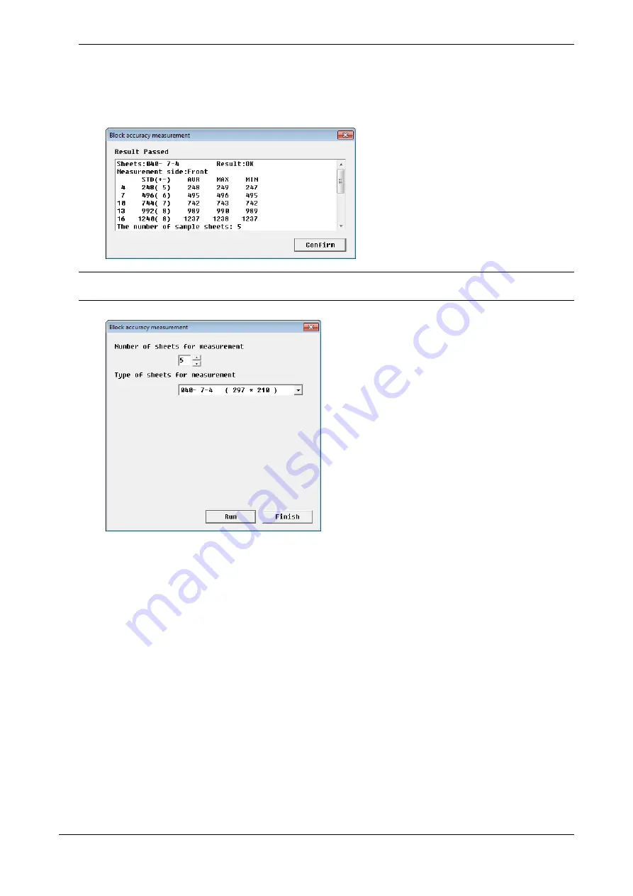
(4)  The measurements of the block precision (bit) and the judgment result are displayed.


Threshold for judgment: 

Line 4: ±5bit


Line 7: ±6bit


Line 10: ±7bit


Line 13: ±8bit


Line 16: ±8bit


(5)  Click [Confirm].


(6)  Click [Finish].


If the result is NG (not OK), check the following items:


 When you set the document, did you move the document guide until it just touches the right side of the 

sheets? 


 Is there any foreign objects attached to the T1 drive roller?


 Is the T1 pinch roller installed properly?


 Are there stains in the OCR TEST SHEET?


*  It may be possible that the OCR TEST SHEET is stretched or shrunk.


Replace the OCR TEST SHEET with new one and start the block precision measurement again.


Summary of Contents for ImageTracDS 1210

Page 1: ...Version 1 1 ImageTracDS 1210 1155 Maintenance Manual...

Page 2: ...Maint 00 0000 Maintenance Manual for ImageTracDS 1155 1210 Image Scanner This maintenance procedure includes information about periodic maintenance and how to replace components...

Page 3: ...nslated version of the document This English version is a preliminary documentation release and it differs from the final in important ways Quality control review error correction of the translation m...

Page 4: ...nt in a residential area is likely to cause harmful interference in which case the user will be required to correct the interference at his own expense Ibml does not take on any responsibility for any...

Page 5: ...ning Ultrasonic Sensor SS Sensor assembly L5 M5 Maint 03 0130 3 3 9 Applying grease on Gear S P Replacement Gear S P Maint 03 0140 4 Diagnostic Functions Maint 04 0000 4 1 Diagnostic Items for Each Op...

Page 6: ...Maint 07 0350 8 Parts Replacement Procedure Maint 08 0000 8 1 Preparation Maint 08 0000 8 1 1 How to remove or attach the covers Maint 08 0000 8 1 2 How to remove or attach the guides Maint 08 0040 8...

Page 7: ...lutch Maint 08 0740 8 3 36 Replacing Extension Plate Maint 08 0750 9 Checking and Adjustment Maint 09 0000 9 1 Checking tensions of belt Maint 09 0000 9 2 Checking Upper Guide Gap Maint 09 0020 9 3 Ch...

Page 8: ...Maint 00 0060 Revision History REV Date Corrected by Checked by Approved by Description 1 01 26 2016 Ibml Support Support OEM 1 1 7 6 2016 Ecn 27 Mn Mn Error correction 00 0020...

Page 9: ...is not directly related to safety General safety precautions Precautions before starting work Maintenance work may be performed only trained and qualified personnel Be sure to follow the instructions...

Page 10: ...re starting work Just switching off the machine power supplies is usually not enough When power is fed from a wall or floor outlet unplug the power supply cord or turn off the switch on the power dist...

Page 11: ...ric current by cutting the power at the source disconnecting the power cable or turning the power OFF by pressing the power switch If it is impossible use a nonconductive object e g dry wooden stick t...

Page 12: ...m of the device If you hold other parts such as the Input Tray or Output Tray the device may break or drop When placing the device on the floor be careful not to catch your fingers between the bottom...

Page 13: ...gargle and contact the nearest medical service Maint 08 0340 When you replace the Gas Spring work with opening the Main Unit Don t remove the Gas Spring on both sides at one time because the Main Uni...

Page 14: ...the new version is correct to ensure the correct update If you download a file in Start mode 2 after the downloaded program is programmed the device will restart Do not turn off the device even when...

Page 15: ...er you save the file In the dump file you can keep data other than waveform data Maint 07 0250 Be sure to remove and attach the parts in accorance with the described procedure When removing or attachi...

Page 16: ...Maint 00 0140 Safety Notice Label on device Clean each safety notice labels regularly so the text be read clearly If the label is broken replace with a new label...

Page 17: ...Maint 00 0150 Left side Rear side Rear side Left side This mark shows following CAUTION Caution on high temperature The parts become high temperature Work after cooling them down enough...

Page 18: ...nent Names and Functions 3 Periodic Inspection and Maintenance Items Lists ofwork items for a periodic inspection 1 Introduction 7 Diagnosis Run when the host system is connected 5 Stand Alone Operati...

Page 19: ...lection Sensor PC41 Fig31 2 Reflection Sensor PC41 Reflection Sensor PC41 sensor 3 3 7 6 5 1 8 3 19 Imprinting Gate Control and Jam Monitoring Detector sensor PC42 Reflection Sensor PC42 Fig33 5 Refle...

Page 20: ...PS774 PK assembly Panel PCB 6 5 1 8 3 5 Panel Operation LED indicator Front Side Image Sensor Image Sensor Front CIS_Unit_assembly Front Fig2 7 CIS Unit assembly CIS Unit assembly Front CIS Unit assem...

Page 21: ...Maint 01 0030...

Page 22: ...ing the right side of the documents put on the Input Tray Output Tray L Scanned documents are ejected to this tray The host system specifies which Output Tray is used as the tray where documents are e...

Page 23: ...tch Used for turning on or off the power switch of Scanner Usually the main power switch is kept ON I side and turn ON OFF the device by the Power Switch If you do not use the device for a long time t...

Page 24: ...green red 0 0 5 1 1 5 2 2 5 s Dump Download System failure Lit green green red 0 0 5 1 1 5 2 2 5 s Standby Green and red alternate flashing 2 green red 0 0 5 1 1 5 2 2 5 s Diagnostic mode Imprint Tes...

Page 25: ...rmittently and subsequently drives the Pick Roller intermittently through the idler gear The Reverse Roller is driven by the Motor assembly Reverse With the Thin Sheed Scanning setting the Pick Roller...

Page 26: ...S Control CIS SERAIL FLASH 128KB Time Controlled IO Port FPGA Motors Sensors Inkjet Printers MAIN PCB assembly CPS878 CIS Unit assembly DRV PCB assembly CPS880 a IC1 d IC50 c IC3 b IC2 Sub IO Port FPG...

Page 27: ...or Reverse motor Main motor HM TM RM MM J8 and J11 are not used IL Cover switch PC41 PC42 PC41R Display panel Operation Button LED indicator J401 CPS774 PCB assembly J609 J601 J603 R SOL assembly J607...

Page 28: ...ng Gear in Feeder separator unit Apply greese to the shaft of the Gear S P and the tooth of the clutch gear When there is a tooth jump sound or worn out tooth replace the gear 3 3 9 8 2 1 3 Check afte...

Page 29: ...expiration date is printed on the package If you use ink cartridge after the expiration date print quality may be deteriorated We recommend you open ink cartridge just before you install it A warning...

Page 30: ...eign objects on the CIS Unit assembly Front and CIS Unit assembly Back with gauze or the like When scanning the front side has a problem clean the glass surface of the CIS Unit assembly Front and remo...

Page 31: ...Pick Unit assembly Figure 1 2 Cleaning the Reverse Roller a Meticulously remove paper dust and other objects attached to the surface of the Reverse Roller with gauze wet wipes or the like Confirm tha...

Page 32: ...ce are removed 3 3 4 Cleaning Pinch Roller 1 Check for foreign objects on the surface of the Pinch Roller T1 referring to 2 3 Mechanical Unit The Pinch Roller T1 consist of plastic bearings Delrin bea...

Page 33: ...Imprinting Head Pin Platen Imprinting Head pin 1 Remove the Ribbon cassettle Clean debris on the Imprinting Head Pin using the brush 2 Open the Top Unit and clean the Platen using gauze soaked in eth...

Page 34: ...artridge Back a Open the Imprint Cover Back Move the lever on the IJP assembly in the direction of the arrow b Move the lever on the Ink_Jet_Print_assembly in the direction of the arrow c Use one hand...

Page 35: ...rocedure After you clean cartridge follow the instruction in 10 1 2 Imprint Test to confirm that the printer works properly Unit Cleaning Procedure Remarks Control Unit Wipe the unit off gently using...

Page 36: ...print quarity is not improved after cleaming of Control Unit and Nozzle Unit wipe the metal terminal of the IJP assembly off gently using a clean cloth cotton swab or the like Top Unit Imprinting Cove...

Page 37: ...sensor PC21L Senosr PC21R sensor PC31 sensor a Operate the Main Latch Button and open the Main Unit b Remove paper dust and other objects attached to the plastic tip of each sensor with gauze PC21L s...

Page 38: ...gauze wet wipes or the like and clean the PC11 sensor with it Be careful not to pinch your fingers d Open the Reverse Cover Wrap your finger with gauze and clean the PC20 sensor with it e Close the M...

Page 39: ...43 senosr PC51 sensor PC52 sensor a Operate the Top Latch Button and open the Top Unit b Remove paper dust and other objects attached to the plastic tip of each sensor with gauze PC41 sensor PC42 sens...

Page 40: ...opriate width paper so that the paper can insert between the rollers Then repeatedly insert and remove the paper between the rollers to clean the sensor d Close the Top Unit by pushing the PUSH labels...

Page 41: ...ition detection may be affected and malfunction may result a Operate the Main Latch Button and open the Main Unit b Remove paper dust attached to the surface of the SS_Sensor_assembly shown in the fig...

Page 42: ...points on the gear tooth as shown below Replace Gear S P In the case there is a tooth jump sound or worn out tooth Replace the Gear S P attached the Pick Top Cover as follows 2 Attach the Pick Unit a...

Page 43: ...d If the Scanner failed or you are replacing parts see 4 1 Diagnostic Items for Each Operation and 4 2 Diagnostic Order for Parts Replacement and follow the instruction given Diagnostic Function Stand...

Page 44: ...S878 PCB The MAIN PCB assembly CPS878 PCB is replaced 4 3 Replacing Main PCB assembly CPS878 8 3 1 Replacing Main PCB assembly CPS878 PCB DRV PCB assembly CPS880 PCB The DRV PCB assembly CPS880 PCB is...

Page 45: ...tion of white level 3 6 7 2 2 8 Calibration of feeding speed 3 6 7 3 2 9 Measurement of USB data transfer rate 2 6 8 3 Diagnosis 7 3 1 Logging Information Print 1 7 2 3 2 Work Information Display 2 4...

Page 46: ...y CPS878 PCB The scanner will be restarted automatically after the download is finished Wait until the scanner is on standby 7 4 Download 7 Diagnosis Load Store Device Unique Information Start mode 2...

Page 47: ...B replacement Turn on the power 6 Diagnosis Download Execute this step if a control program comes with the maintenance part If not this step is not required Download the control program to the Main PC...

Page 48: ...rol program to the MainPCB assembly The scanner will be restarted automatically after the download is finished Wait until the scanner is on standby 7 4 Download 5 Entering estimates Calculate the esti...

Page 49: ...ice unique information and cannot record the latest information This case happens mostly because of failure in Main PCB Instead of loading the device unique information you need to enter information m...

Page 50: ...t date YYYYMMDD Pick roller Count sheets Pick roller Judgement 0001000000 sheets Separator roller Count sheets Separator roller Judgement 0001000000 sheets Reverse roller Count sheets Reverse roller J...

Page 51: ...y Item Value Unit Replacement date YYYYMMDD Pick roller Count 1 sheets Input the worked date Pick roller Judgement 0001000000 sheets Separator roller Count 2 sheets Input the worked date Separator rol...

Page 52: ...ntenance mode The table below shows the item for stand alone operation Item Operation Item Function Summary Applicable Case Reference 1 Local Test The test sheet is scanned by the stand alone Scanner...

Page 53: ...green green red 5 Set the OCR TEST SHEET No 040 7 4 on the Inpur Tray The Input Tray is automatically elevated and a scan test starts During a scan test the LED indicator flashes green If the scan tes...

Page 54: ...s Mechanical operation Moves the mechanical drive system including motors as you command This function is mostly used for isolating a failure location in the mechanical drive system Calibration of sca...

Page 55: ...steps depending on the OS installed on the host system 1 For Windows 7 Click the Start button of the Windows From the menu select All Programs ImageTracDS 1210 Scanner Utility for Service Personnel a...

Page 56: ...Maint 06 0020 2 Click the Miscellaneous Tool in Utility for Service Personnel tab 3 The Miscellaneous Tool window is displayed Select the diagnostic item and click Run...

Page 57: ...document guide until it just touches the right side of the sheets and then click Run 2 Click Yes After the program is loaded the process automatically starts 3 When the following message is displayed...

Page 58: ...The threshold for judgment is 7bit If the measurement is this value or less the result is OK The amount of skew change bit compared to Line 1 is measured at Lines 4 7 10 13 and 16 The and signs indica...

Page 59: ...document guide until it just touches the right side of the sheets and then click Run 2 Click Yes After the program is loaded the process automatically starts 3 When the following message is displayed...

Page 60: ...ot OK check the following items When you set the document did you move the document guide until it just touches the right side of the sheets Is there any foreign objects attached to the T1 drive rolle...

Page 61: ...ay of calibration information The learning result for the device is displayed 1 Select Scanner for Input mode and OFF for Output mode and click Run When you want to exit click Confirm The screen goes...

Page 62: ...or image level inputted the scanner with the ratio Determination value within the range of 898 1455 3 About Feeding Speed calibration Marks at 11 locations in the OCR TEST SHEET are scanned The veloci...

Page 63: ...ult The LED on the photo sensor PCxx is turned on OFF The LED on the photo sensor PCxx is turned off Input Tray position F L Scanning position L L Default Standby position 1 If ON is selected the scan...

Page 64: ...Input Tray up to the scanning position for the check Note If you already know the switch is broken we recommend you move the pick unit up and down manually and check the level change L L Input Tray p...

Page 65: ...Scanner light source Back Light off Default 1 If Light on is selected the scanner lamp flashes with the motor operation 2 The level of the ultrasonic sensor is displayed and refreshed every couple of...

Page 66: ...on the previous page 2 1 sheet Threshold to 511 0 The threshold is displayed in the level display window 3 2 sheets 0 to threshold 1 4 0 sheets 02 OFF 0 to 70 For reference only The level should be c...

Page 67: ...sonic sensors are equipped Select each senor or all sensors in the setting window Ultrasonic sensor No 1 5 selectable which one The level of specified senor is displayed All The levels of all senors a...

Page 68: ...peed1 High Speed Default Speed2 Speed3 Speed4 Low Speed 3 Operation mode 3 Setting How the motor operates Stop condition Continuous Default Continuous rotation mode Only by clicking Pause Interval A R...

Page 69: ...nt to stop the operation click Pause 3 Click OK 4 Click Finish Then the Mechanical Operation window closes By clicking Pause the operation other than the motor operation is also reset and the screen g...

Page 70: ...king Pause If clicked the Input Tray stops at the L L DOWN position UP F L The Input Tray moves up to F L DOWN L L The Input Tray moves down Position for short feeding Level1 The Input Tray moves down...

Page 71: ...t Output Tray L U Those two positions are switched about every 0 6 seconds Stopped by clicking Pause Accept side Output Tray L The gate is moved so that the sheets are ejected to the Output Tray L pos...

Page 72: ...000 Maximum Item Option Note 1 Feed speed Speed1 High Speed Speed2 Speed3 Speed4 Low Speed Default Speed 1 High Speed 2 Output Tray Output Tray L Accept Tray Output Tray U Reject Tray Accept Reject al...

Page 73: ...n You can check the series of feeder operation from feeding paper process to ejecting paper process for the supported sheet size from the minimum to the maximum Check if the feeder operation is normal...

Page 74: ...click Finish 1 Scanning position Movement of CIS Unit assembly Front Remarks White Default The CIS_Unit_assembly FRONT Front image sensor moves towards the front Input Tray side of the device and sto...

Page 75: ...Front especially whether the CIS Unit assembly Front can reach the white side Remove the Main Cover L at the side of the device so that you can check the movement of the CIS Unit assembly Front a Whit...

Page 76: ...et Scanning is enabled 1 Specify the parameters and click Run The motor operates in the specified mode If you want to stop the mechanical operation click Finish 1 Operation Pick Unit assembly operatio...

Page 77: ...ghting the LED 1 Specify the parameters and click Run The LED operates in the specified mode If you want to stop the mechanical operation click Finish 2 When terminates Mechanical operation the light...

Page 78: ...7 3 Calibration of feeding speed 1 On the Calibration of scanner window select Auto Calibration and click Run 2 Usually leave the Date of measurement and Number of sheets for measurement as they are S...

Page 79: ...set five sheets of the test sheet 040 7 4 in the following direction on the Scanner and click Yes 6 The scanner starts scanning the sheets and runs the calibration of feeding speed 7 When the followi...

Page 80: ...etails of results about each calibration see 6 7 2 Calibration of white level and 6 7 3 Calibration of feeding speed If all results are OK the calibration results are written automatically in the scan...

Page 81: ...replacing CIS Unit assembly 1 On the Calibration of scanner window select Calibration of white level and click Run 2 Usually leave the Date of measurement and Number of sheets for measurement as they...

Page 82: ...Execute the following Handling NG Not Good cases Calibration results show each ratio of front back and R G B between White Background part on the CIS Unit assembly and color level of the OCR TEST SHE...

Page 83: ...rethane rubber has increased due to no carbon liquid chemical and a feeding error occus 1 On the Calibration of scanner window select Calibration of Feeding Speed and click Run 2 Usually leave the Dat...

Page 84: ...Maint 06 0300 4 The scanner starts scanning the sheets and runs the calibration of feedig speed 5 When the following message is displayed set the test sheets 040 7 4 again on the Scanner and click Yes...

Page 85: ...Good case 1 Clean the T1 roller Check whether a sheet can move smoothly in the feeder unit See 3 3 3Cleaning Drive Roller and 3 3 4Cleaning Pinch Roller In the case of paper is fed too fast The diame...

Page 86: ...urement of USB data transfer rate 1 Click Run 2 Click Confirm The transfer rate depends on specification or configuration of host PC If the transfer speed is insufficient confirm the connection of USB...

Page 87: ...elect All Programs ImageTracDS 1210 Scanner Utility for End User and then click the Scanner Utility b For Windows 8 8 1 Select ImageTracDS 1210 Scanner on start screen after showing all Apps in Window...

Page 88: ...every sheet run the Imprint Test until printed properly 1 For the Specifying sheet size click the Regular size Or click the Specified size and type in the paper size If you scan the Regular size shee...

Page 89: ...side the Characters for Imprint Back are B 0123456789 by default You can change print characters The number of printable character is up to 16 The printable characters are numbers 0 9 alphabet A Z and...

Page 90: ...inter a Confirm the installation of the ink ribbon cassette b Clean the Imprinting Head Pin and Platen See 3 3 5 Imprinting Head Pin Platen c Check and adjust the Imprinting Gap See 9 6 Adjusting the...

Page 91: ...rint Settings and click the Execute The Ink Cartridge Settings window is displayed In the window The number of printed sheets Sheets about currently using ribbon cassette and ink cartridge and Ink lev...

Page 92: ...ink cartridge for the scanner equipped rear imprinter 3 After you replace the ink cartridge in the Information display window checkmark the Ink level reset for the ink cartridge you replaced Then cli...

Page 93: ...The number of printed sheets is 0 Sheets Cartridge replacement date is updated New ink cartridge should be checked to print out characters properly by running the Imprint Test 7 Run the 6 9 2 Imprint...

Page 94: ...Used for updating the control program firmware of the Scanner Option Settings Shows the model name and the special order options of the Scanner This function allows you to set up and change the model...

Page 95: ...host system 1 Launch the Diagnosis Menu For Windows7 Click Start button of the Windows From the menu point to All Programs ImageTracDS 1210 Scanner Utility for Service Personnel and then click Diagnos...

Page 96: ...onitor of the host system The error information can be also printed out 1 Select List output mode and press Enter If you specify 2 for List output mode the Logging Information List window is displayed...

Page 97: ...Maint 07 0030 4 After the last window is displayed the window is displayed to ask you whether to clear the logging file Specify the parameter and press Enter 5 Click OK...

Page 98: ...de 1 Display is used when you want to display the operation information 2 Maintenance1 is used when you want to clear the relative values after you replace periodic replacement parts You cannot enter...

Page 99: ...t 07 0050 3 Click OK Startup mode 2 Maintenance1 1 Specify 2 for Start mode Enter the security code SETTEI and press Enter 2 Now you can modify some values for the replaced component to 0 Then press E...

Page 100: ...s and then goes into the standby mode Do not turn off the power of the Scanner Startup mode 3 Maintenance2 1 Specify 3 for Start mode Enter the security code SETTEI and press Enter 2 Now you can modif...

Page 101: ...Maint 07 0070 3 Click OK 4 The scanner restarts and then goes into the standby mode Do not turn off the power of the Scanner...

Page 102: ...wnload is finished After the device restarts wait until the device goes into the standby mode Used for updating the control program firmware of the Scanner Start mode 1 Version display shows the progr...

Page 103: ...for the CD ROM is E 2 The following window is displayed Confirm that the new version shown in the window and the version for your purpose are the same If the version is correct press Enter 3 During d...

Page 104: ...nd confirm that the version for your purpose is working Referrence to have two versions of control program in the device The scanner has two versions of control program firmware and valid control prog...

Page 105: ...s used to directly change the settings if for some reason loading and storing the settings is not possible when you replace the Main PCB assembly CPS878 Shows the model name and the special order opti...

Page 106: ...e scanner For the Special Order options marked with black in the Option Label 1 should be indicated in the window Then press Enter 4 Click OK 5 If the model name the options and or the Special Order o...

Page 107: ...code SETTEI and press Enter 2 Enter the model name as shown below and the options as shown in the Option Label on the back of the scanner Press PageDown or select Next Page Page Down in the window wit...

Page 108: ...n in the Option Label on the back of the scanner If a Special Order option is marked with black in the Option Label enter 1 Then press Enter 4 Click OK 5 The scanner restarts and then goes into the st...

Page 109: ...unique information back to the new Main PCB assembly CPS878 when you replace the Main PCB assembly CPS878 setup the settings directly using 7 4 Work Information Display and 7 7 Option Settings Refere...

Page 110: ...n already stored to the host system before a window will opens to confirm overwriting the file is OK If the device and the host system are the same as before select 2 Continue For the periodic inspect...

Page 111: ...ss Enter The device unique information stored in the host system is loaded to the Scanner 2 Click OK The scanner restarts and then goes into the standby mode after loading finishes Wait until the devi...

Page 112: ...onditions and displays the waveform 7 7 2 Saving Waveform Data Saves the captured waveform data in the CSV format 7 7 3 Loading Waveform Data from Saved Data Loads the saved waveform data CSV format a...

Page 113: ...orm menu 2 The Option Settings window is displayed Select each item in the Option Settings window Set an A4 sheet on the Input Tray horizontally landscape You can use a commercially available copy pap...

Page 114: ...and image capture are executed and displayed Not Scan Image capture is not executed No sheets are necessary Only waveform data is displayed Specify Name of Format File For each of the front and back s...

Page 115: ...creen You can select a window and check various display data You can check the details of Result for the measurement data in the Measurement Results window The displayed waveform can be magnified hori...

Page 116: ...the file name immediately after you save the file 1 To execute this function click Save Data button or select Save Data in the File menu Button File menu 2 When this function is executed the Save As w...

Page 117: ...Waveform menu Button Waveform menu 2 When this function is executed the Selection window is displayed to select the waveform data Select the waveform data file CSV format from the save location and c...

Page 118: ...Maint 07 0240 The loaded waveform data will be displayed...

Page 119: ...py the saved file to another folder immediately after you save the file In the dump file you can keep data other than waveform data 1 To execute this function click From Dump Data button or select Fro...

Page 120: ...If loading waveform data from the dump files finishes successfully the message is displayed to indicate loading the data finishes successfully Click OK The waveform data in the dump files is displaye...

Page 121: ...layed Move or copy the dump files from the IBML HTSCNDR ETC32 folder to any folder in the following screen the folder name if DUMP You need to copy all files necessary for display In the case of the S...

Page 122: ...t The left center right in the waveform and Dirt Check Data on the Waveform Diagnosis window mean for both front and back sides as seen from the front of the device Note On the image of the back side...

Page 123: ...ning inside the device Cleaning and check of the white level reference label There should be no scratches or peeling off Cleaning of the glass surface of the CIS Unit assembly For information about cl...

Page 124: ...action Cleaning inside the device Cleaning and check of the white level reference label Removing paper dust Cleaning of the glass surface of the CIS Unit assembly For information about cleaning see 3...

Page 125: ...action Cleaning inside the device Cleaning and check of the mold part of the CIS Unit assembly There should be no scratches or the like Cleaning of the glass surface of the CIS Unit assembly For infor...

Page 126: ...h part select Scan in Scan Image in the Option Settings window and execute it If you do not find any white area in the background of the captured image Figure C 2 the Scanner works fine You can stop c...

Page 127: ...ce of the CIS Unit assembly White dust attach the black mold part of the CIS Unit assembly Corrective action Cleaning inside the device Cleaning of the mold part of the CIS Unit assembly Cleaning of t...

Page 128: ...enu This function offers the same operation as a scanner utility Image Sensor Test used by a user Note If you load the data using From Saved Data and From Dump Data in Waveform menu this function does...

Page 129: ...pped from the factory This stored waveform will be displayed This waveform is used to check whether the data stored in the CIS Unit assembly when the device is shipped from the factory is corrupted en...

Page 130: ...may occur Work after turning OFF the device and removing the power cable Caution on high temperature Some parts may become hot Work after cooling them down enough Top Cover 1 Remove 4 washer faced he...

Page 131: ...5 Attach the Main Cover L using the above steps in reverse Main Cover R 1 Operate the Top Latch Button and open the Top Unit 2 Operate the Main Latch Button and open the Main Unit 3 Remove 3 washer f...

Page 132: ...L using the above steps in reverse Side Cover R 1 Remove the Top Cover and Main cover R 2 Remove 3 washer faced head screws 305 fixing the SideCover R 3 Remove the Side Cover R in the arrow direction...

Page 133: ...e Top Cover and Main cover L R Side Cover L R 2 Remove 6 bind head screws SB306N fixing the Back Cover 3 Slide the Back Cover in the direction A and then remove the Back Cover in the direction B 4 Att...

Page 134: ...nough Top Guide2 assembly 1 Remove the Top Cover See 8 1 1 How to remove or attach the covers 2 Disconnect the PC42 and PC52 sensor connector and then operate the Top Latch Button and open the Top Uni...

Page 135: ...ver L R See 8 1 1 How to remove or attach the covers 2 Remove 4 bind head screws SB306N and then remove the Eject Giude assembly 3 Attach the Eject Guide assembly using the above steps in reverse Ejec...

Page 136: ...Remove 2 bind head screws SB308N fixing the Front Cover and then remove the Front Cover Be careful with the length of the screw 4 Remove 4 bind head screws SB306N fixing the Upper Guide assembly and...

Page 137: ...the Upper Guide Back assembly lower it and remove it by pulling it forward Note When removing the Upper Guide assembly be careful not to drop the Upper Guide Back assembly on the rear image sensor CI...

Page 138: ...ews SB306N fixing the Front Guide assembly lift the Front Guide assembly up disconnect the connector of the PC21 sensor and remove the Front Guide assembly 5 Attach the Front Guide assembly using the...

Page 139: ...n the relay board unlock the clamp remove 4 bind head screws SB306N fixing the Lower Guide assembly lift the Lower Guide assembly up and remove the Lower Guide assembly 4 Attach the Lower Guide assemb...

Page 140: ...e upper part of the Pick_Cover and pull down in the direction of the arrow to open the Pick Cover 3 Lift up the Pick Unit assembly and pull it toward to remove 4 Install the Pick Unit assembly with ca...

Page 141: ...assembly Then remove the parts in order 4 Attach using the above steps in reverse Oiles Drymet LF Separator Washer 3 Separator Roller spacer E ring TW003 Oiles Drymet LF Separator Separator Clutch Sep...

Page 142: ...e Pick Shaft assembly Then remove the parts in order 4 Attach using the above steps in reverse Pick Roller E ring TW003 Pick Gear Pick Shaft Parallel pin The convex part should be left side looking fr...

Page 143: ...rom the Pulley Sparate a Separator Roller is just inserted without glue so you can remove it with your hand and replace it 2 Install Separator Rollers using the above steps in reverse Install a Separa...

Page 144: ...e to both sides of the shafts and 3 points on the gear tooth as shown below Applying part both sides of the shafts Applying part both sides of the shafts Gear S P Remove the Gear S P in the allow dire...

Page 145: ...on and open the Main Unit 2 Open the Reverse Cover and remove the Reverse Roller assembly 3 Remove the E ring TW005 fixing the Reverse Roller assembly Then remove the parts in order 4 Attach using the...

Page 146: ...ll a Reverse Roller in order for the Pulley Reverse and the Reverse Roller to fit together completely rotate the Reverse Roller with your palm a couple of times while pushing it strongly 4 Fully inser...

Page 147: ...bly to be replaced to new one Caution on high temperature Some parts may become hot Work after cooling them down enough 1 Remove the Top Cover Main Cover L R Side Cover L R and Back Cover See 8 1 1 Ho...

Page 148: ...2 bind head screws SB306N divide the PCB box and remove only the Main PCB assembly part 7 Remove 6 bind head screws SB306N fixing the Main PCB assembly remove only the Main PCB assembly 8 Attach usin...

Page 149: ...CB cover See 8 3 1 Replacing MAIN PCB assembly CPS878 PCB step 2 3 Remove the PCB box See 8 3 1 Replacing MAIN PCB assembly CPS878 PCB step 3 through 5 4 Disconnect all 5 connectors N1 CN6 CN8 CN10 CN...

Page 150: ...ng or removing the cables hold the connector unit to avoid damaging the wire Note When pulling the lever of the J608 connector to insert or remove the FPC cables operate the center of the lever Note R...

Page 151: ...rse When attaching be careful with the direction of the connectors and the route of the cables Cable route Correct direction Wrong direction J607 J603 J607 J603 J607 J603 How to remove J603 and 607 Pu...

Page 152: ...ted to the Relay PCB assembly Note When inserting or removing the cables hold the connector unit to avoid damaging the wire 3 Remove 2 bind head screws SB306N fixing the Relay PCB assembly CPS881 PCB...

Page 153: ...or attach the covers 2 Remove the J401 connector 3 Remove 1bind head screw SB306N fixing the CPS774 PK assembly Panel PCB and remove the CPS774 PK assembly Panel PCB 4 Attach the CPS774 PK assembly Pa...

Page 154: ...and open the Main Unit 3 Open the Stopper Hopper Base lift the Input Tray up in the direction A and remove the Input Tray in the direction B 4 Attach using the above steps in reverse Removing Input T...

Page 155: ...ng the Output Tray hold the stacker with one hand and remove the Output Tray in the arrow direction with another hand 4 After removing the Output Tray Upper remove the Output Tray Lower as the same pr...

Page 156: ...e Output Tray hold the Output Tray Guide up slightly to avoid the bump 2 Right side Slide the Output Tray Guide to the left edge in the direction A and remove the Output Tray Guide in the direction B...

Page 157: ...rward with pressing the part shown below and remove the CIS Unit assembly downward Note Be careful not to apply too much force when removing the CIS Unit Note Be careful that the SPRING CIS in the Hol...

Page 158: ...RING CIS Holder Block I Press the CIS Unit assembly toward II Slide the CIS Unit assembly toward Note Be careful that the SPRING CIS might spring III Remove the CIS Unit assembly and SPRING CIS from t...

Page 159: ...reverse with inserting the convex part of the ARM CIS into the concave part of the CIS Unit assembly 10 After replacement run 6 7 2 Calibration of white level ARM CIS convex CIS Unit assembly concave...

Page 160: ...connect the J201 Connector 6 Attach the CIS Unit assembly toward the front after connecting the J201 Connector When connecting J201 Connector be sure to insert the J201 Connector securely 7 Insert the...

Page 161: ...ont Cover and Upper Guide assembly See 8 1 2 How to remove or attach the guides 4 Remove 3 bind head screws SB306N fixing the SS Sensor assembly M5 Receiver and remove the SS Sensor assembly M5 Receiv...

Page 162: ...o remove or attach the guides 4 Remove 3 bind head screws SB306N fixing the SS Sensor assembly L5 Transmitter and remove the SS Sensor assembly L5 Transmitter 5 Disconnect the connector on the SS Sens...

Page 163: ...k the 2 Cable Clamps 4 Operate the Top Latch Button and open the Top Unit 5 Remove 2 bind head screws SB306N fixing the IJP assembly Rear and remove the IJP assembly Rear 6 Disconnect the J501 Connect...

Page 164: ...ck Rear 3 Remove the Ink Pad Pack Rear from the Ink Pad Bracket as not to leave a double sided tape and clean the Ink Pad Bracket Use for example gauze dampened with absolute ethanol to remove the tap...

Page 165: ...rt or remove the FPC cables operate the center of the lever 4 Disconnect the J607 Connector connected to the DRV PCB assembly CPS880 PCB Note When disconnecting the J607 connector pull the connector u...

Page 166: ...picture 9 Replace the Imprinting Head DC motor 10 Remove 2 bind head screws SB306N fixing the DC motor and remove the DC motor 11 Replace the DC motor 12 Attach using the above steps in reverse after...

Page 167: ...w one 6 Remove 1 E ring TW005 fixing the Drive Roller M T2 shift the Drive Roller M T2 to the right remove the Drive Roller M T2 and replace new one In the same way remove one E ring TW005 to fix the...

Page 168: ...4 Remove the Reverse Roller assembly with lifting it up See 8 2 2 Replacing Reverse Roller assembly 5 Loosing the washer faced head screws 305 fixing the Reveres Spring Support and lower the Reverse S...

Page 169: ...ly the Reverse assembly may interfere with other parts In this case check the removal direction and then remove the Reverse assembly again If the Reverse assembly is removed forcibly the parts may get...

Page 170: ...ee 8 1 1 How to remove or attach the covers 2 Remove each spring and then remove 2 bind head screws SB306N each fixing the Main Button assembly and Main Latch R 3 Attach using the above steps in rever...

Page 171: ...Remove 2 bind head screws SB408N each remove Latch Hook assembly L and Latch Hook assembly R 3 Attach using the above steps in reverse 4 After replacement check the gap for the guide referring to 9 2...

Page 172: ...t Tray 3 Remove the Front Guide assembly See 8 1 2 How to remove or attach the guides 4 Unlock the Cable Clamp remove 1 bind head screw SB306N fixing the PC11 assembly and remove the PC11 assembly 5 D...

Page 173: ...the Motor assembly Pick See 8 3 22 Replacing each Motor assemblies 6 Remove sensors to be replaced Remove the hook fixing the Sensor Reception PC11 sensor disconnect the connector and remove the Sens...

Page 174: ...d remove the PC20 L sensor assembly 5 Disconnect the connector of the Sensor Emission PC20 sensor 6 Remove the hook fixing the Sensor Emission PC20 sensor and remove the Sensor Emission PC20 sensor 7...

Page 175: ...ove the Reflection Sensor PC21L PC21R sensor 5 Disconnect each of the cables from each of the sensors 6 Attach using the above steps in reverse Fit the hole of Photo plate to the positioning bump Note...

Page 176: ...or PC31 sensor and remove the Reflection Sensor PC31 sensor 4 Remove the cable attaching the Reflection Sensor PC31 sensor When attaching use the removed cable 5 Attach using the above steps in revers...

Page 177: ...1 washer faced head screw 302 fixing the Reflection Sensor PC41 sensor and remove the Reflection Sensor PC41 sensor 4 Disconnect the connector from the Reflection Sensor PC41 sensor 5 Attach using th...

Page 178: ...ensor PC43 sensor disconnect the connector and remove the Reflection Sensor PC43 sensor Remove 1 washer faced head screw 302 fixing the Reflection Sensor PC51 sensor removed hook fixing the Reflection...

Page 179: ...he Reflection Sensor PC52 sensor 7 Remove 1 washer faced head screw 302 fixing the Reflection Sensor PC52 sensor 8 Remove the hook fixing the Reflection Sensor PC52 sensor and remove the Reflection Se...

Page 180: ...tach the covers 2 Remove 1 washer faced head screw 302 fixing the bracket PC52 and remove the bracket PC52 3 Disconnect the connector of the Sensor Reception PC52sensor 4 Remove the hook fixing the Se...

Page 181: ...Cover and Pick Unit assembly See 8 2 1 Replacing Pick Unit assembly 4 Remove the Upper Guide assembly See 8 1 2 How to remove or attach the guides 5 Disconnect the connector of the Photo Interrupter F...

Page 182: ...de assembly See 8 1 2 How to remove or attach the guides 4 Disconnect the connector of the Photo Interrupter L L sensor 5 Remove the hook fixing the Photo Interrupter L L sensor and remove the Photo I...

Page 183: ...rew SB306N at the R SOL assembly side fixing the R SOL assembly and Gate Shaft and remove the R SOL assembly 5 Attach using the above steps in reverse When attaching the R SOL assembly insert the groo...

Page 184: ...2 E rings TW007 fixing the Gas Spring and remove the Gas Spring 3 Attach using the above steps in reverse Be careful with the direction of the Gas Spring Note Do not use removed E rings when attachin...

Page 185: ...cing Input Tray 3 Remove the Front Guide assembly See 8 1 2 How to remove or attach the guides 4 Remove 2 bind head screws SB406N fixing the Motor assembly Hopper and the connector of the Motor assemb...

Page 186: ...bind head screws SB406N fixing the Motor assembly Eject remove the Motor assembly Eject 4 Attach using the above steps in reverse 5 Check tension of belt of belts of Eject motor See 9 1 Checking Tens...

Page 187: ...teps in reverse When attaching the Motor assembly fix 2 bind head screws SB306N with pressing the Motor assembly in the arrow direction downward Note Be careful with the order to attach the belts of t...

Page 188: ...Cover See 8 1 2 How to remove or attach the guides 4 Remove 2 bind head screws SB406N fixing the Motor assembly Pick and the connector of the Motor assembly Pick and then remove the Motor assembly Pi...

Page 189: ...d Main Cover R See 8 1 1 How to remove or attach the covers 2 Remove the connector of the Motor assembly Brake 3 Remove 2 bind head screws SB306N fixing the Motor assembly Brake and remove the Motor a...

Page 190: ...the Motor assembly Reverse and the connector of the Motor assembly Reverse and then remove the Motor assembly Reverse 5 Attach using the above steps in reverse with fitting the positioning hole to th...

Page 191: ...or attach the guides 4 Remove the E ring TW004 for fixing and Gear ELE Shaft 5 Remove the Parallel Pin and E rings TW004 at both sides 6 Remove the Elevator assembly 7 Attach using the above steps in...

Page 192: ...ve of the R SOL assembly to the collar and attach the R SOL assembly on the Gate Shaft assembly 7 Fix 1 bind head screw SB306N with pressing the Gate Shaft assembly in the arrow direction downward 8 A...

Page 193: ...Pick Unit assembly 5 Remove the Upper Guide assembly See 8 1 2 How to remove or attach the guides 6 Remove 2 washer faced head screws 302 fixing the Pinch Roller T1 assembly and remove the Pinch Rolle...

Page 194: ...collar 4 Remove 2 E rings TW004 and remove the S2M Belt Brake and 2 2GT Pulley 18 D s 5 Attach using the above steps in reverse Note Do not use removed E rings when attaching Use new ones 6 Check ten...

Page 195: ...T5 T6 1 Remove the Top Cover Main Cover L R and Side Cover L R See 8 1 1 How to remove or attach the covers 2 Remove the the MXL Belt T5 T6 3 Attach using the above steps in reverse MXL Belt T5 T6 Ne...

Page 196: ...se DC Fan for DRV PCB 1 Remove the Top Cover and Main Cover L R See 8 1 1 How to remove or attach the covers 2 Remove the Eject Guide assembly See 8 1 2 How to remove or attach the guides 3 Disconnect...

Page 197: ...r attach the covers 2 Remove the PCB cover See 8 3 1 Replacing Main PCB assembly CPS878 PCB 3 Disconnect the J15 connector on the Main PCB assembly 4 Remove 2 bind head screws SB320N fixing the DC Fan...

Page 198: ...per Lower See 8 3 7 Replacing Output Trays and Output Tray Guide 3 Disconnect the connector of the PC51 sensor 4 Remove 4 bind head screws SB306N fixing the R Stacker Back R assembly F2 5 Remove the A...

Page 199: ...8 1 2 How to remove or attach the guides 4 Remove the Reverse Cover form the Front Guide assembly using a Flat blade small as shown below 5 To attach the Reverse Cover attach A part which has long pro...

Page 200: ...e Feed Drive assembly 6 Remove the MXL Belt Pick 7 Remove 2 bind head screws SB306N fixing the Feed Drive assembly and remove the Feed Drive assembly 8 Attach using the above steps in reverse Be caref...

Page 201: ...ver and Upper Guide assembly See 8 1 2 How to remove or attach the guides 5 Close the Pick Cover and remove the Pick Cover with pressing the fulcrum parts inward 6 Attach the Pick Cover into the fulcr...

Page 202: ...the arrow direction 4 Attach using the above steps in reverse Note When attaching the Mini Latch put the spacer between the Mini Latch and metal plate Note When attaching the Release Button be sure t...

Page 203: ...onnector of the Cover Switch and remove the Cover Switch assembly 4 Attach new Cover Switch assembly temporarily 5 Close the Main Unit and Top Unit 6 With pressing the Cover Switch to the metal plate...

Page 204: ...move 1 E ring TW004 5 Remove the MXL Belt Pick 6 Remove the Replacing Belt Pulley Clutch with rotating it in the arrow direction counterclockwise 7 Attach using the above steps in reverse Note Do not...

Page 205: ...e Input Tray and Output Tray Upper 3 Insert new Extension Plates between Extension Tray 1 and Extension Tray 2 of the Input Tray and Output Tray Upper with the expanded side to the top Note With sligh...

Page 206: ...on Gauge 5N 2mm P 1 2 2 4N Loosen the indicated screw and adjust the belt tension pressing the Motor assembly Brake in the arrow direction S2M Belt Brake Motor assembly Brake Pressing direction Screw...

Page 207: ...T1 in the arrow direction Motor assembly Main 2mm P 0 9 2 1N Loosen the indicated screw and adjust the belt tension pressing the Motor assembly Main in the arrow direction MXL Belt T1 Motor assembly...

Page 208: ...wnward and fix the screws for the Latch Hook assembly R Take the same step for the opposite side After adjusting the gap apply a small amount of greese to the both shafts of the Latch Hook assembly L...

Page 209: ...ss the Top Unit downward and fix the screws for the hook holder Take the same step for the opposite side After adjusting the gap apply a small amount of greese to the both shafts of hook holder Check...

Page 210: ...L Cover Switch is 0 When the Top Unit or Main Unit is opened I L Cover Switch is 1 Referring to the following picture when the metal parts are not contancted loosen the bind head screw SB306N press i...

Page 211: ...ultiple sheets feeding Tend to cause mis feeding Clean rollers frequently If there is a warp or bend in sheets straighten them Small document Document which is hard to separate Standard Normal Front S...

Page 212: ...m in thickness contacts with the Thicnes Gause of 1 mm in thickness mearure a value of the Tension Gauge 6 The measured value the pressure of the Reverse Rollers should be 4 3 0 1 N 430 10 g If the va...

Page 213: ...ead assembly should be leaning towards the left and fix 2 bind head screws SB306N If the two are not touching each other use the long hole on the Imprinting Head assembly to adjust it Then tighten the...

Page 214: ...NMB 1 Remove 2 bind head screws fixing the Ribbon Holder and remove the Ribbon Holder 2 Loosen 2 bind head screws fixing the DC Motor NMB and attach the DC Motor NMB by pressing in the arrow directio...

Page 215: ...Cassette is loose at step 5 bend the holding section slightly inwards as shown in the picture below holding section 5 Make sure the Ribbon Cassette is firmly inserted into the Ribbon Holder 4 Importa...

Page 216: ...indow 1 2 Imprint Test Executes an Imprint Test to check that ink cartridge is ready for printing Executes the Imprint Test for both front and rear side The steps of cleaning rear ink cartridge can be...

Page 217: ...enu select All Programs ImageTracDS 1210 Scanner Utility for End User and then click the Scanner Utility b For Windows 8 8 1 Select ImageTracDS 1210 Scanner on start screen after showing all Apps in W...

Page 218: ...Maint 10 0020 2 The Menu window of Scanner Utility below is displayed...

Page 219: ...displayed 2 Open the device with the Main Latch Button Clean the glass and the Black White Background parts on both Image Sensors Front Back Close the device 3 Click the Contamination Check to check...

Page 220: ...Maint 10 0040 4 If the Result box shows the levels of the image sensors are OK Click the End button Then return to the Menu Window 5 Click the End to return to the Menu Window...

Page 221: ...Menu Window select the Imprint Test and click the Execute The Imprint Test window is displayed The followings are default settings Sheet size A4 Landscape Imprint Not print For the Specifying sheet s...

Page 222: ...ont side the Characters for Imprint Front are F 0123456789 by default You can change print characters If you select the Back side the Characters for Imprint Back are B 0123456789 by default You can ch...

Page 223: ...take a following action For front side imprinting a Confirm the installation of the front ribbon cassette b Clean the Imprinting Head Pin and Platen See 3 3 5 Cleaning Imprinting Head Pin Platen c Che...

Page 224: ...roller 2 Press the How to replace the Pick roller button the How to replace the Separator roller button or the How to replace the Reverse roller button for the rollers to be replaced Replacement proc...

Page 225: ...Maint 10 0100 4 Click the Yes 5 Click the OK 6 Confirm that the Sheet counts are reset to 0 and that the replacement date has been updated...

Page 226: ...et count settings and Roller replacement warning timing setting 1 In the Sheet Counter Settings window select the Parameter Settings tab 2 Checkmark the Roller replacement sheet count settings to allo...

Page 227: ...ant to suppress the roller replacement warning checkmark the Roller replacement warning timing setting and select the Do not report 4 Click the Execute to update the setting 5 In the window below clic...

Page 228: ...number of printed sheets Sheets and Cartridge replacement date about currently using ribbon cassette or ink cartridge are displayed In the window The number of printed sheets Sheets of front ribbon ca...

Page 229: ...0140 3 If you replace the rear ink cartridge in the Information display window checkmark the Ink level reset for the rear ink cartridge Then click the Execute 4 In the window below click the Yes 5 Cli...

Page 230: ...r of printed sheets is 0 Sheets Cartridge replacement date is updated New ink cartridge should be checked to print out characters properly by running the Imprint Test New ink cartridge should be check...

Page 231: ...meter Settings tab to set rear parameters 2 Select the Ink level warning timing setting or Ink replacement warning timing setting check box to allow updating corresponding settings 1 Then click the Ex...

Page 232: ...Maint 10 0170 3 In the window below click the Yes 4 Click the OK 5 Confirm that the settings are changed correctly in the Parameter Setting window...

Page 233: ...window is displayed In the window Transition time to the power save mode is displayed 2 To change the transition time specify the value between 1 and 240 in minutes and click the Execute 3 In the wind...

Page 234: ...1 In the Menu Window select the USB Operation Mode and click the Execute The USB Operation Mode window is displayed In the Transfer mode Super Speed USB3 0 or Hi Speed Full Speed USB2 0 is displayed 2...

Page 235: ...ontamination level select the sensitivity setting from the menu Normal Normal sensitivity recommended Level 1 3 Lower sensitivity the larger the number the lower the sensitivity becomes Do not report...

Page 236: ...usion of the Scanner or damaged by a metal part of the Scanner Take off your valuable belongings while you work If warning message about consumable roller is displayed or the sheet count exceeds the R...

Page 237: ...and open the Main Unit 2 Hook your fingers on the upper part of the Pick Cover and pull down in the direction of the arrow to open the Pick Cover 3 Lift up the Pick Unit assembly and pull it toward to...

Page 238: ...t assembly 6 Replace rollers referring to the next page 7 Install a pick Roller using the above steps in reverse Pick Roller has no mounting direction 8 Close the Main Unit by pushing the PUSH labels...

Page 239: ...strongly Replacing Separator Rollers 1 Remove the Separator Roller from the Pulley Separate a Separator Roller is just inserted without glue so you can remove it with your hand and replace it 2 Insta...

Page 240: ...Main Unit 2 Hock your fingers on the edge of the Reverse Cover assembly 3 Pull the Reverse Cover assembly in the direction of the arrow to open the Reverse Cover assembly 4 Lift up the Reverse Roller...

Page 241: ...ounting direction 7 After you install a Reverse Roller in order for the Pulley Reverse and the Reverse Roller to fit together completely rotate the Reverse Roller with your palm a couple of times whil...

Page 242: ...ce the Ribbon Cassette Or Ribbon Cassette and Imprinter may be damaged 1 Operate the Top Latch Button and open the Top Unit 2 Press the PUSH OPEN mark on the Imprint Cover Front at the left side to op...

Page 243: ...de position Only in the case of the Ribbon Cassette Tray is at inside position 5 Pull out the Ribbon Cassette 6 Push the Ribbon Cassette Tray to the inside position where the Ribbon Cassette Tray stop...

Page 244: ...Tray carefully so the Tip does not get stuck Push it until you hear a clicking sound 9 Set the Tray to the original position in instruction 3 10 Close the Imprint Cover Front 11 Close the Top Unit by...

Page 245: ...medical service 10 4 1 Exterior View and Component Names The ink cartridge unit consists of ink cartridge and the Ink Jet Print assembly The Ink Jet Print assembly is used to hold the ink cartridge to...

Page 246: ...artridge Leave ink cartridge in a place subject to exposure to direct sunlight Recommended actions while scanning In the environment with low temperature and low humidity especially in winter printed...

Page 247: ...on of ink cartridge 1 Open a package and take out ink cartridge The ink cartridge is packed in a pair of cases as shown in the figure below You need to keep those cases for later use For details see 1...

Page 248: ...ar on the Top Unit 2 Move the lever on the Ink Jet Print assembly in the direction of the arrow and release the ink cartridge fixed 3 Grab the knob on the ink cartridge and pull the ink cartridge upwa...

Page 249: ...ink cartridge 2 Grab the knob on the ink cartridge and insert the ink cartridge from front side A boss protrudes from the ink cartridge so do not force the ink cartridge into the position 3 Move the...

Page 250: ...t into the cases the nozzle side metal face must be at the side pointed by the arrow printed on the cases Put the ink cartridge and the cases together into a commercially available plastic bag and sto...

Reviews: