Pipe and hose configurations can vary. You can determine the best configuration for your
installation by analyzing the needs of your facilities, or a site preparation representative can
provide this analysis.
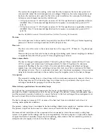
Flexible hoses are needed to supply and return water between your hard plumbing (manifolds
and coolant distribution units) and the heat exchanger (allowing needed movement for opening
and closing the rack rear door).
Hoses are available that provide water with acceptable pressure-drop characteristics and that help
prevent depletion of some corrosion inhibitors. These hoses must be made of peroxide-cured
ethylene propylene diene monomer (EPDM) rubber, non-metal oxide material and must have
Parker Fluid Connectors quick-connect couplings at one end, which are attached to the heat
exchanger, and must either have a low impedance quick connect coupling or nothing to attach to
a barb at the other end. The Parker couplings are compatible with the heat exchanger couplings.
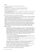
Hose lengths 3 - 15 meters (10 - 50 ft), in increments of 3 meters (10 ft), are available. Hoses that
are longer than 15 meters (50 ft) might create unacceptable pressure loss in the secondary circuit
and reduce the water flow, reducing the heat removal capabilities of the heat exchanger.
Use solid piping or tubing that has a minimum inner diameter of 19 mm (0.75 in.) and the fewest
possible joints between a manifold and a heat exchanger in each secondary loop.
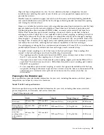
Use quick-connect couplings to attach the hoses to the heat exchangers. Hose couplings that
connect to the heat exchanger must have the following characteristics:
v
The couplings must be constructed of passivated 300-L series stainless steel or brass with less
than 30% zinc content. The coupling size is 19 mm (0.75 in.).
v
The supply hose must have a Parker (male) quick-coupling nipple, part number SH6-63-W, or
equivalent. The return hose must have a Parker (female) quick-connect coupling, part number
SH6-62-W, or equivalent.
v
If a low impedance quick-connect coupling is used at the opposite (manifold) end of the hose,
use positive locking mechanisms to prevent loss of water when the hoses are disconnected. The
connections must minimize water spill and air inclusion into the system when they are
disconnected.
Planning for the 7965-S42 rack
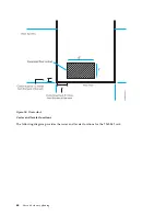
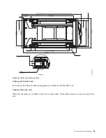
Rack specifications provide detailed information for your rack, including dimensions, electrical, power,
temperature, environment, and service clearances.
Model 7965-S42 rack specifications:
Hardware specifications provide detailed information for your rack, including dimensions, electrical,
power, temperature, environment, and service clearances.
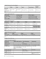
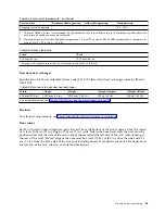
Table 80. Dimensions for rack
Width
Depth
Height
Weight (Empty)
EIA unit
capacity
Rack only
600 mm (23.6
in.)
1070 mm (42.1
in.)
2020 mm (79.5 in.)
166 kg (365 lb)
42 EIA units
Rack with two
standard doors
600 mm (23.6
in.)
1132 mm (44.6
in.)
2020 mm (79.5 in.)
177 kg (391 lb)
42 EIA units
Rack with rear
door heat
exchanger (dry)
and standard
doors
600 mm (23.6
in.)
1231 mm (48.5
in.)
2020 mm (79.5 in.)
210 kg (463 lb)
42 EIA units
Site and hardware planning
61
Summary of Contents for 8408-44E
Page 1: ...Power Systems Site and hardware planning IBM...
Page 2: ......
Page 3: ...Power Systems Site and hardware planning IBM...
Page 16: ...xiv Site and hardware planning...
Page 18: ...2 Site and hardware planning...
Page 22: ...6 Site and hardware planning...
Page 51: ...Figure 19 Model 0555 and 7014 S25 plan view Site and hardware planning 35...
Page 192: ...176 Site and hardware planning...
Page 204: ...188 Site and hardware planning...
Page 205: ......
Page 206: ...IBM Printed in USA...

