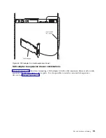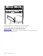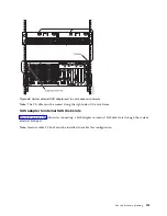
Cable management
These guidelines ensure that your system and its cables have optimal clearance for maintenance and
other operations. The guidelines also provide guidance in correctly cabling your system and using the
appropriate cables.
The following guidelines provide cabling information for installing, migrating, relocating, or upgrading
your system:
v
Position drawers in racks to allow enough space, where possible, for cable routing on the bottom and
top of the rack, and between drawers.
v
Shorter drawers should not be placed between longer drawers in the rack (for example, placing a
19-inch drawer between two 24-inch drawers).
v
When a specific cable plugging sequence is required, for example, for concurrent maintenance
(symmetric multiprocessing cables), label the cables appropriately and note the sequence order.
v
To facilitate cable routing, install cables in the following order:
1.
Power cables
2.
Communications (serial attached SCSI, InfiniBand, remote input/output, and peripheral component
interconnect express) cables
Note:
Install and route the communications cables, starting with the smallest diameter first and
then progressing to the largest diameter. This applies to installing them into the cable management
arm and retaining them to the rack, brackets, and other features that may be provided for cable
management.
v
Install and route the communications cables, starting with smallest diameter first and then progressing
to the largest diameter.
v
Use the innermost cable-management bridge lances for power cables.
v
Use the middle cable-management bridge lances for communications cables.
v
The outermost row of cable-management bridge lances are available for use when routing cables.
v
Use the cable raceways on the sides of the rack to manage excess power cables.
v
There are four cable-management bridge lances on the top of the rack. Use these bridge lances to route
the cables from one side of the rack to the other, by routing to the top of the rack, where possible. This
routing helps to avoid having a cable bundle that blocks the cable exit opening at the bottom of the
rack.
v
Use the cable management brackets provided with the system to maintain concurrent maintenance
routing.
v
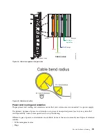
Maintain a minimum bend diameter of 101.6 mm (4 in.) for communications (SAS, IB, and PCIe)
cables.
v
Maintain a minimum bend diameter of 50.8 mm (2 in.) for power cables.
v
Use the shortest-length cable available for each point-to-point connection.
v
If cables have to be routed across the rear of a drawer, leave enough slack to reduce the tension on the
cables for maintenance of the drawer.
v
When routing cables, leave enough slack around the power connection on the power distribution unit
(PDU) so that the wall-to-PDU line cord can be attached to the PDU.
v
Use hook-and-loop fasteners where necessary.
120
Site and hardware planning
Summary of Contents for 8408-44E
Page 1: ...Power Systems Site and hardware planning IBM...
Page 2: ......
Page 3: ...Power Systems Site and hardware planning IBM...
Page 16: ...xiv Site and hardware planning...
Page 18: ...2 Site and hardware planning...
Page 22: ...6 Site and hardware planning...
Page 51: ...Figure 19 Model 0555 and 7014 S25 plan view Site and hardware planning 35...
Page 192: ...176 Site and hardware planning...
Page 204: ...188 Site and hardware planning...
Page 205: ......
Page 206: ...IBM Printed in USA...

