background image

ibidi Pump System

7.3.2

Settings within the PumpControl Software

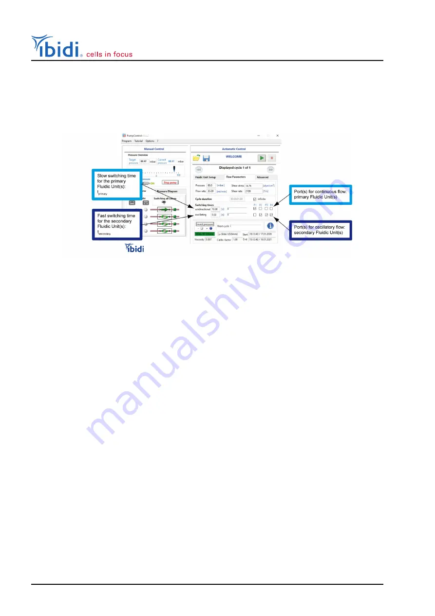
Because the switching times are different for the primary and the secondary Fluidic Units, the Pump-
Control software must be programmed accordingly. Figure

43

shows how to correctly set the corre-

sponding parameters.

Figure 43: Settings of the PumpControl Software, when applying oscillatory flow
to one primary and three secondary Fluidic Units. The ports P1 - P4 are the ports
on the back of the Pump controller.

• Choose your setup in the ”Fluidic Unit Setup” tab (Perfusion Set, slide, and viscosity). Click on

”Apply new settings”.

• Enter the required shear stress or flow rate in the respective box (tab ”Flow Parameters”).

• Set the check boxes in the line ”oscillatory” for the Fluidic Unit with oscillatory flow.

• Set the switching time for oscillatory switching (e.g., 1 second for an oscillation of 0.5 Hz).

• Press the start button to start the experiment.

For details please refer to the

PumpControl

instructions.

7.3.3

Oscillatory Experiment with Four Fluidic Units

For an experiment using one primary Fluidic Unit and three oscillatory secondary Fluidic Units, the
Oscillatory Flow Kit for four Fluidic Units is required (Figure

44

top right).

The setup is similar to the setup with two Fluidic Units. Please follow all steps as described in Section

7.3.1

for two Fluidic Units.

The air pressure is distributed by the primary Fluidic Unit to the secondary Fluidic Units by splitting
it between valve block (V1) and the tubing leading to the Perfusion Set (Figure

44

).

Version 2.6 (May 12, 2022)

56

Instruction Manual

Summary of Contents for ibidi Pump System

Page 1: ...Version 2 6 Instruction Manual ibidi Pump System ibidi com...

Page 2: ...ump System Contact ibidi GmbH Lochhamer Schlag 11 82166 Gra felfing Germany Phone 49 89 520 46 17 0 Fax 49 89 520 46 17 59 E mail info ibidi de Internet ibidi com Version 2 6 May 12 2022 2 Instruction...

Page 3: ...oHS Compliance Statement 13 1 10 1 EU Directive WEEE 13 1 10 2 EU Directive RoHS 13 1 11 Regulatory Statement 14 2 Intended Use of the ibidi Pump System 15 3 Equipment 16 3 1 Components of the ibidi P...

Page 4: ...idic Unit 38 6 3 Filling the Perfusion Set with Medium 41 6 4 Remove Air Bubbles from the Perfusion Set 42 6 5 Pinch Test 43 6 6 Calibration of the Flow Rate 43 6 6 1 Connect the Calibration Slide to...

Page 5: ...rol Software 56 7 3 3 Oscillatory Experiment with Four Fluidic Units 56 7 4 Pulsatile Flow Experiments 58 8 Technical Details 60 8 1 Working Principle of the ibidi Pump 60 8 2 Positive Versus Negative...

Page 6: ...usion Set 73 10 2 3 Cells Detach under Flow Conditions 74 10 3 Imbalanced Medium 74 10 4 Medium Runs in One Direction Only 75 10 5 No Connection Between ibidi Pump and PumpControl Software 76 10 6 Pre...

Page 7: ...l words WARNING CAUTION and NOTE have specific meanings in this man ual Do not proceed beyond a signal word until you have performed the indicated actions WARNING A potentially hazardous situation whi...

Page 8: ...nd current to Flu idic Unit min DC 14 V 590 mA Standby current 60 mA Max current 1000 mA Max current with 4 Fluidic Units 1475 mA Operating Conditions of the ibidi Pump System Operating area Enclosed...

Page 9: ...ower supply to wall 1 2 m power supply to device Electrical cable FU to pump 2 0 m Air pressure tubing 2 0 m Air pressure tubing drying bottle 2 1 and 0 6 m Pressure Range of the ibidi Pump Total pres...

Page 10: ...ol unit must be inserted in an outlet with a ground earth contact Do not replace detachable power cables by power cables with inadequate specifications By violating these instructions you risk electri...

Page 11: ...ssing equipment and machine tools Avoid dust and corrosive gas Do not install the ibidi Pump System where it could be exposed to high levels of dust or to outside air or ventilation outlets Install th...

Page 12: ...ishes tubes fluidic connectors reagents etc The warranty for all parts supplied and repairs provided under this warranty expires on the warranty expiration date of the original product 1 8 Transportin...

Page 13: ...ve The symbol indicates that this product must be recycled dis posed of separately from other household waste It is the end user s responsibility to dispose of this product by taking it to a designate...

Page 14: ...claration Laborger t laboratory equipment ibidi Pump System ibiPump 2 Der oben beschriebene Gegenstand erf llt die Vorschriften der Richtlinie 2011 65 EU vom 08 Juni 2011 zur Beschr nkung der Verwendu...

Page 15: ...e ibidi Pump System offers the following advantage for cell culture under flow Covering of the whole physiological range of shear stresses Precise control of flow conditions with the PumpControl softw...

Page 16: ...needed The details are listed below 10903 Fluidic Unit Switching valves for various flow assays suitable for all Perfusion Sets and channel Slides 10904 Fluidic Unit Quad 4 Fluidic Units on a stable...

Page 17: ...idic Units The following parts must be ordered separately Sterile Perfusion Sets Sterile Slides Luer Type 3 2 ibidi Pump The ibidi Pump can generate air pressure up to 100 mbar The most precise workin...

Page 18: ...Rear view of the ibidi Pump with rear air port USB and power supply port and Fluidic Unit cable ports 3 3 Fluidic Unit The Fluidic Unit holds the Perfusion Set fluidic reservoirs and tubing and perfor...

Page 19: ...s Reservoir Holder Cat No Compatible Perfusion Sets Cat No for Fluidic Unit 10 ml for Fluidic Unit Quad 10 ml 10976 10986 Perfusion Set RED Perfusion Set YELLOW GREEN Perfusion Set ORANGE Perfusion Se...

Page 20: ...Pinch Valve The pinch valve V2 at the front of the Fluidic Unit squeezes the tubing that is inserted into its slots with a movable bar pinching off the inserted tubing parts and thus blocking fluid fl...

Page 21: ...adapters can be connected to any suitable flow chamber with Luer connec tors Figure 7 Sterile packaged Perfu sion Set Perfusion Set Parts Figure 8 a Sterile air filters modified 0 2 m Teflon b Syringe...

Page 22: ...ters Elbow Luers and slides are not autoclavable and must be removed be fore autoclaving or replaced with new parts Replacement reservoirs Filter Reservoir Sets 10971 10972 10974 and the Elbow Luer Co...

Page 23: ...general flow assays The Slide I Luer 3D is designed for perfusing a cell monolayer on a gel matrix The Slide Spheroid Perfusion offers three channels with 7 small wells each for the long term cultivat...

Page 24: ...cm2 5 4 cm2 Slide I 0 6 Luer 0 6 mm 150 l 2 5 cm2 5 6 cm2 Slide I 0 6 Luer Glass Bottom 0 65 mm 162 5 l 2 5 cm2 5 6 cm2 Slide I 0 8 Luer 0 8 mm 200 l 2 5 cm2 5 8 cm2 Slide I 0 8 Luer Glass Bottom 0 8...

Page 25: ...2 Luer 2 0 ml min 27 0 ml min 7 5 dyn cm2 95 0 dyn cm2 Slide I 0 2 Luer Glass 3 1 ml min 36 0 ml min 7 5 dyn cm2 82 0 dyn cm2 Slide I 0 4 Luer 4 2 ml min 47 0 ml min 4 0 dyn cm2 43 0 dyn cm2 Slide I 0...

Page 26: ...ed values for the Slide y shaped refer to the single channel area see Application Note 18 Perfusion Set Orange Viscosity 0 0072 dyn s cm2 Flow rate Shear stress Temperature 37 C Min Max Min Max Withou...

Page 27: ...values for the Slide y shaped refer to the single channel area see Application Note 18 Perfusion Set White Viscosity 0 0072 dyn s cm2 Flow rate Shear stress Temperature 37 C Min Max Min Max Without a...

Page 28: ...Slide y shaped refer to the single channel area see Application Note 18 Perfusion Set Yellow Viscosity 0 0072 dyn s cm2 Flow rate Shear stress Temperature 37 C Min Max Min Max Without any slide 0 16 m...

Page 29: ...alues for the Slide y shaped refer to the single channel area see Application Note 18 Perfusion Set Brown Viscosity 0 0072 dyn s cm2 Flow rate Shear stress Temperature 37 C Min Max Min Max Without any...

Page 30: ...nifit cap 2 Pass approximately 2 cm of the black marked tube through the hole in the Omnifit cap 3 Slide the filter bubbler on the end of the black marked tube 4 Remove the stock cap from the drying b...

Page 31: ...Using a laptop configured and approved by ibidi will ensure that all settings are correct We cannot provide troubleshooting for a computer that was not set up by ibidi The system require ments for th...

Page 32: ...luidic Unit inside the incubator 5 Connect the air front port of the pump to the air pressure input of the Fluidic Unit via the 2 m air pressure tubing 6 Connect the Fluidic Unit to the ibidi Pump via...

Page 33: ...ted to the Fluidic Unit with the elec trical cable and air pressure tubing The setup using positive pressure which is recommended 1 is shown in Figure 13 Figure 13 Positive pressure system setup of on...

Page 34: ...ric cable is plugged into any of the Fluidic Unit ports on the back of the pump The pump will automatically recognize which port is connected If using positive pressure connect the Fluidic Unit direct...

Page 35: ...stall the software on a different computer follow the instructions below Important The power and update options on a computer running PumpControl must be set so as not to interfere with the software D...

Page 36: ...s imperative to use the included power supply and USB cable 1 Power up the ibidi Pump with the power supply To verify that power is connected check the Power LED status on the front panel Figure 17 2...

Page 37: ...de the incubator one day before starting the experiment Sterility is maintained as long as the packaging is not opened Slides within the packaging Perfusion Set s within the packaging Cell culture med...

Page 38: ...proper insertion the sections of the tubing are marked with colored tabs Figure 19 It is best to mount the Perfusion Set on the ster ile working bench immediately before filling the Perfusion Set wit...

Page 39: ...ed from the front Slightly squeeze the reservoirs for easy insertion Figure 22 4 Begin with the valve s right side slots Insert the two sections of the tubing coming from reser voir B into these slots...

Page 40: ...move it up and down Stretch the tubing only between the y connectors to ensure the tubing is not disconnected Figure 26 Verify that the Perfusion Set is mounted correctly Check that the tubes are ins...

Page 41: ...inar flow hood 2 First connect the air pressure tubing to the reservoir filters Figure 27 and then pull off both filters from the syringe 3 Fill in the required amount of medium ap propriate for the P...

Page 42: ...bles start the pump with the PumpControl software Refer to the software manual for detailed instructions 1 Equilibrate the liquid levels of the two reservoirs using the manual control panel in the Pum...

Page 43: ...ove switching state 1 2Yes 2No Does the liquid move switching state 2 2Yes 2No If the answers are No in both cases the insertion is correct If the liquid is moving in one or both of the positions chec...

Page 44: ...he same type as in your experiment without cells must be connected to the Perfusion Set 1 Check the tubing for air bubbles and use the hose clip to clamp both tubing arms of the Perfu sion Set tubes d...

Page 45: ...want to apply 2 Set all experimental parameters in the automatic control panel accordingly Perfusion Set Slide and required shear stress Note down the flow rate and pressure that are calculated autom...

Page 46: ...or the calibration factor to be set at 1 then click the Apply Settings button 3 Proceed to the Flow Parameters tab Enter the shear stress 10 dyn cm2 in the respective box The flow rate 23 8 ml min and...

Page 47: ...ting calibration factor 1 131 Figure 35 Recalibration dialog in the PumpControl software The recalibration factor affects the relationship between pressure and resulting flow rate Figure 36 Figure 36...

Page 48: ...them recover before initiating flow To start flow place the whole assembly Fluidic Unit and slide in the incubator and connect the Fluidic Unit to the pump air pressure tubing and electric cable Start...

Page 49: ...at 5 ml 1 ml 2 Disconnect the Fluidic Unit air pressure tubing and electric cable and move it to a sterile flow hood 3 Perform the medium exchange see the two options below 4 Transfer the Fluidic Uni...

Page 50: ...ibidi Pump System 4 Fill both reservoirs to the 5 ml 1 ml mark with fresh medium Figure 38 Complete medium exchange Version 2 6 May 12 2022 50 Instruction Manual...

Page 51: ...g Branched air tubing for use with two three or four Fluidic Units is supplied with the pump Connect the Fluidic Units with the pump via the Splitter Set as shown in Figure 39 example with 4 Fluidic U...

Page 52: ...6 7 Note the flow rate in your documentation 8 Perform step 2 to 7 for each Fluidic Unit 9 Finally calculate a mean flow rate for all Fluidic Units For reproducible results the variation of the measur...

Page 53: ...All secondary Fluidic Units can apply oscillatory or unidirectional flow Table 23 Possible setups of oscillatory flow depending on the number of available Fluidic Units Number of Fluidic Units Possibl...

Page 54: ...ure 42 3 5 Connect the pump and the two Fluidic Units with the Fluidic Unit cables In this example Port 1 on the Pump Controller for the primary Fluidic Unit and Port 2 on the Pump Controller for the...

Page 55: ...Perfusion Set or insert some tubing pieces into the primary Fluidic Unit s pinch valve V2 to protect it A1 A2 B1 B2 1 3 B A 2 1 2 1 2 Figure 42 Setup of the oscillatory flow with two Fluidic Units on...

Page 56: ...t the check boxes in the line oscillatory for the Fluidic Unit with oscillatory flow Set the switching time for oscillatory switching e g 1 second for an oscillation of 0 5 Hz Press the start button t...

Page 57: ...m A3 A4 B3 A2 B2 A1 B1 B4 1 3 A B 2 1 2 3 4 1 2 3 4 A1 A2 A3 A4 A B1 B2 B3 B4 B Figure 44 Oscillatory flow setup with four Fluidic Units one primary and three secondaries Instruction Manual 57 Version...

Page 58: ...ss with the help of the PumpControl software 5 Route the tubing of the Perfusion Set which is coming out of the first Fluidic Unit through the pinch valve of the second Fluidic Unit Make sure that you...

Page 59: ...Pump System Figure 46 PumpControl example setting for pulsatile flow Note Pulsatile flow experiments work best with Perfusion Sets with long tubing 50 or 100 cm Instruction Manual 59 Version 2 6 May 1...

Page 60: ...e results in a specific flow rate ml min that is dependent on the pressure input the viscosity of the medium and the flow resistance of the perfusion system tubing and slide 3 The specific flow rate m...

Page 61: ...rough the lower loop of the Perfusion Set The channel is perfused from left to right In State 2 valve V1 is set such that the pressurized air is applied to reservoir B while the outlet of reservoir A...

Page 62: ...iched in CO2 For an optimal CO2 supply a tubing is connected to the rear port and leads into the incubator to such in the CO2 enriched incubator atmosphere When using this setup make sure to use the d...

Page 63: ...below shows an overview of the differences between positive and negative pressure Positive Pressure recommended Negative Pressure Contamination Less likely More likely CO2 To reach the desired CO2 le...

Page 64: ...e standard Fluidic Unit operation creates a continuous and unidirectional flow within the Slide channel The working principle is detailed in Section 8 1 Oscillatory Flow Some experiments require an os...

Page 65: ...37 C 30 difference The viscosity of water in relation to temperature is shown in Figure 51 1 mPa s 0 01 dyn s cm2 Figure 51 Viscosity of water as a function of temperature 8 5 Shear Stress Calculation...

Page 66: ...tom 104 7 Slide I 0 6 Luer 60 1 Slide I 0 6 Luer Glass Bottom 51 5 Slide I 0 8 Luer 34 7 Slide I 0 8 Luer Glass Bottom 31 0 Slide VI 0 4 176 1 Slide VI 0 5 Glass Bottom 99 1 Slide VI 0 1 10 7 l min Ve...

Page 67: ...the shear stress Depending on the chan nel geometry and the viscosity of the medium the relation between flow rate and shear stress is linear detailed in the formula in Application Note 11 Thus after...

Page 68: ...time Example The sticky Slide channels are not available in the drop down menu of the software The formulas to calculate the shear stress can be found in the sticky Slide instructions The example show...

Page 69: ...n the software Figure 53 Selection of Perfusion set red and Slide selection without any slide Figure 54 Inserting 18 7 mbar in the pressure box The flow rate is 13 3 ml min as indicated in the calibra...

Page 70: ...Pump System Switchingtime 60 s min 5 ml 60 s min 5 ml 13 3 ml min 22 5s Insert the value of 22 s in the box Switching times unidirectional slightly rounded down Version 2 6 May 12 2022 70 Instruction...

Page 71: ...hours The beads will turn orange once all moisture has been removed After they cool to room temperature they can be returned to the drying bottle for use 9 3 Replacement Filters for Perfusion Sets The...

Page 72: ...bubbles were introduced while filling the tubing before connecting the channel slide with cells To remove air bubbles in the tubing start a cycle in PumpControl with a high flow rate or load the Re mo...

Page 73: ...s in low channels for only a few hours If the cells need to be in the channel for more than a few hours refresh the medium in the channel in short intervals or place the slide on a rocking plate The c...

Page 74: ...another lot or passage of cells Primary cells espe cially are very variable in their fitness The cell number in the slide was too low Cells could not form a confluent layer and were detached from the...

Page 75: ...ing by view and remove any potential material that could block the tubing Blockage in one of the short tubing pieces inserted into the pinch valve V2 Replace with a fresh Perfusion Set Blockage in the...

Page 76: ...d PumpControl Software Issue When applying settings in the PumpControl software the pump does not react e g no pressure output no valve switching Possible Cause Solution Program is running in demo mod...

Page 77: ...air pas sage When filters come in contact with medium the air flow is decreased or ceases Filters that are contaminated with medium must be re placed Section 9 3 When applying low pressure even a sin...

Page 78: ...that the tube is inserted properly Pinch valve V2 is not switching Check the functionality of the pinch valve when switching the valve via the PumpControl software the movement of the pinching bar ca...

Page 79: ...le is suitable but when encountering connection issues make sure to use the USB cable de livered with the ibidi pump or a double shielded USB cable with the following specifications reversible A male...

Page 80: ...ochhamer Schlag 11 82166 Gr felfing Germany Toll free within Germany Phone 0800 00 11 11 28 Fax 0800 00 11 11 29 International calls Phone 49 89 520 46 17 0 Fax 49 89 520 46 17 59 E Mail info ibidi co...

Reviews: