Configuration
87
Co
nfi
gur
at
io
n
Rationale
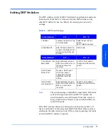
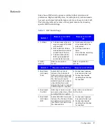
Sites choose DIP switch options according to their priorities and
preferences. High availability sites, for example, may want automatic
bus reset on whereas high performance sites may choose to turn it off.
The following table gives some of the typical reasons for choosing
specific DIP switch settings.
Table 9.
DIP Switch Usage
Switch 1
Reasons to Set OFF
(|)
Reasons to Set ON
(0)
1. Full Bus
a. Full-bus mode is the only
way to access all 14 disks
with one BCC.
b. With two BCCs, full-bus
mode allows two external
connections to the bus.
c. Full-bus mode with two
BCCs gives redundant
environmental services.
a. Split buses allow you to
mirror disks within the
disk system.
b. Split-bus mode uses
fewer
IDs on the bus, improving
bus performance.
2. SES/
SAF-TE
SAF-TE is required
for NT.
SES is required for
HP-UX .
Switch 2
Reasons to Set OFF (|)
Reasons to Set ON (0)
1. Bus Reset-
Hot Swap
Disk
Automatic bus reset
reduces the chances of
data corruption and saves
the 30 to 60 seconds that
the host would spend
determining that a disk is
unavailable. Bus reset
signals the host to resend
outstanding I/O requests.
a. No bus reset reserves
bus control to the host.
b. No bus reset avoids
resetting the entire bus
for one disk.
2. Bus Reset-
Pwr Fail
SCSI bus is held in reset
as power goes down, thus
avoiding data corruption
Bus control is restricted
to the host.
3. Bus Reset-
Hot Swap
BCC
Automatic SCSI bus reset
reduces the chance of data
corruption when a BCC is
inserted or removed from
the disk system.
a. No bus reset reserves
bus control to the host.
b. No bus reset avoids
resetting the entire bus
for one disk.
Summary of Contents for StorageWorks 2300 - Disk System
Page 1: ...hp StorageWorks disk system 2300 Edition E0902 user s guide ...
Page 10: ...10 ...
Page 14: ...14 Product Description ...
Page 35: ...Installation 35 Installation 2 ...
Page 40: ...40 Installation ...
Page 41: ...Installation 41 Installation ...
Page 48: ...48 Installation ...
Page 58: ...58 Installation ...
Page 59: ...Installation 59 Installation 4 Install clipnuts as shown in Figure 28 ...
Page 76: ...76 Installation ...
Page 77: ...Installation 77 Installation ...
Page 83: ...Configuration 83 Configuration 3 ...
Page 86: ...86 Configuration ...
Page 94: ...94 Configuration ...
Page 95: ...Troubleshooting 95 Troubleshooting 4 ...
Page 108: ...108 Removal and Replacement ...
Page 132: ......
Page 134: ......
Page 140: ......
Page 150: ...150 Reference E VCCI Statement Japan Harmonics Conformance Japan F BCIQ EMC Statement Taiwan ...
Page 151: ...Reference 151 Reference G Declaration of Conformity ...
Page 158: ...158 ...

