


Product Description
19
Produ
ct
D
esc
ri
p
tio
n
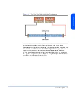
BCCs and BCC Filler Panels
BCCs (Bus Control Cards) plug into two slots in the back of the disk system.
Each BCC connects to both LVD (low voltage differential) buses inside the disk
system. In full bus mode (DIP switch 1 set to “|”), both BCCs have access to all
installed disks. The two SCSI buses are bridged. If either BCC fails and LVM
primary and alternate paths are defined, data can be accessed through the other
BCC. In split bus mode (DIP switch 1 set to “0”), the left BCC (as viewed from
the rear of the disk system), is on the high numbered bank (with disk slots 8, 9,
10, 11,12, 13, and 14) and the right BCC is on the low numbered bank (with disk
slots 0, 1, 2, 3,4, 5, and 6) of disk slots. See Figure 1.
Two SCSI ports (B in Figure 4) on each BCC provide dual LVD connections to
the same or separate hosts. If a host is connected to one of the BCC ports, an
LVD terminator must be connected to the other port on that BCC.
Summary of Contents for StorageWorks 2300 - Disk System
Page 1: ...hp StorageWorks disk system 2300 Edition E0902 user s guide ...
Page 10: ...10 ...
Page 14: ...14 Product Description ...
Page 35: ...Installation 35 Installation 2 ...
Page 40: ...40 Installation ...
Page 41: ...Installation 41 Installation ...
Page 48: ...48 Installation ...
Page 58: ...58 Installation ...
Page 59: ...Installation 59 Installation 4 Install clipnuts as shown in Figure 28 ...
Page 76: ...76 Installation ...
Page 77: ...Installation 77 Installation ...
Page 83: ...Configuration 83 Configuration 3 ...
Page 86: ...86 Configuration ...
Page 94: ...94 Configuration ...
Page 95: ...Troubleshooting 95 Troubleshooting 4 ...
Page 108: ...108 Removal and Replacement ...
Page 132: ......
Page 134: ......
Page 140: ......
Page 150: ...150 Reference E VCCI Statement Japan Harmonics Conformance Japan F BCIQ EMC Statement Taiwan ...
Page 151: ...Reference 151 Reference G Declaration of Conformity ...
Page 158: ...158 ...