background image

Reference

141

Reference

Product Models 

Two models of the disk system are available:

A6490A and A6490AV field-racked (by HP-qualified service engineers)

A6490AE empty field rack disk system

A6490AD deskside disk system

A6490ED empty deskside disk system

A6490AZ factory-racked disk system

6

Summary of Contents for StorageWorks 2300 - Disk System

Page 1: ...hp StorageWorks disk system 2300 Edition E0902 user s guide ...

Page 2: ...can cause hardware or software damage Note Identifies significant concepts or operating instructions this font used for all text to be typed verbatim all commands path names file names and directory names also text displayed on the screen this font used for variables used in commands this font used for GUI menu options and screen controls Trademark Information Red Hat is a registered trademark of ...

Page 3: ...17 Hardware Event Monitoring 17 Components 18 Disk Modules and Disk Module Filler Panels 18 BCCs and BCC Filler Panels 19 Power Supply Fan Module 22 Hardware Software Requirements 24 Topologies 27 Definitions 33 High availability HA 33 Hot pluggable 33 JBOD 33 LVD 33 PDU and PDRU 33 Ultra160 SCSI 34 2 Installation 35 Preparation 36 Electrical Requirements 36 Choosing PDUs 37 contents ...

Page 4: ...nect SCSI and Power Cables 75 Step 7 Install Disk Modules 78 Step 8 Turn on the Disk System 80 Step 9 Verify Devices on the Host 81 Sample IOSCAN 81 Where do you go from here 82 3 Configuration 83 Viewing a Disk System in IOSCAN 84 Sample IOSCAN 84 Setting DIP Switches 85 Rationale 87 Disk Addressing 88 Disk Slots and Addressing 89 Setting Up the Hardware Event Monitor 90 Aliasing Devices HP Quali...

Page 5: ...cal Volume Group Is Active 111 To Determine If the Physical Volume Is Attached 111 To Replace Attached Physical Volumes 112 To Replace Unattached Physical Volumes 114 NT 114 Windows 2000 115 Tools 115 Procedure 115 BCC 119 Tools 119 Procedure 119 BCC Filler Panel 122 Power Supply 123 Tools 123 Procedure 123 Disk System 125 Tools 125 Procedure 125 Top Cover HP Qualified Only 128 Tools 128 Procedure...

Page 6: ...3 Replaceable Parts 144 Specifications 145 Dimensions 145 Weight 145 AC Power Input 146 DC Power Output 146 Heat Output 146 Environment 146 Acoustics 147 Safety Certifications 147 EMC Compliance 147 Regulatory Statements 148 A FCC Statement For U S A Only 148 B IEC Statement Worldwide 148 C Spécification ATI Classe A France 148 D Product Noise Declaration Germany 149 E VCCI Statement Japan 150 Har...

Page 7: ...6 Disk System ContentsDisk System Contents 46 Figure 17 HP Rack System E Rail Kit Contents 48 Figure 18 HP Rack System E Installation Overview 49 Figure 19 Locating the site for the device installation in a System E Rack 51 Figure 20 Installing clipnuts for an HP Rack System E 51 Figure 21 Installing rails in an HP Rack System E 52 Figure 22 Installing the enclosure clipnut 53 Figure 23 Installing...

Page 8: ...cheme for 2 0 Meter Rack 77 Figure 46 Disk Module Installation 78 Figure 47 On Off Switch and System LEDs 80 Figure 48 DIP Switches 86 Figure 49 Disk Module Slots and SCSI Addresses 89 Figure 50 Sample Hardware Event Notification 99 Figure 51 LED Status Indicators 101 Figure 52 Disk System Field Replaceable Units FRUs 108 Figure 53 Disk Module Removal 117 Figure 54 BCC Removal and Replacement 120 ...

Page 9: ... 44 Table 6 Disk System Contents 46 Table 7 Rail Positions for Sequential Disk Systems 50 Table 8 DIP Switch Settings 85 Table 9 DIP Switch Usage 87 Table 10 Disk and BCC SCSI Addresses for Full and Split Bus Modes 88 Table 11 LED Functions 102 Table 12 Troubleshooting Table 104 Table 13 JBOD Enclosure Field Replaceable Units 109 Table 14 Upgrade Products 142 Table 15 PDU PDRU Products 143 Table 1...

Page 10: ...10 ...

Page 11: ...nts are easy to upgrade and maintain Disks power supply fan modules and bus control cards BCCs are replaceable parts that plug into individual slots in the front and back of the disk system Redundant power supply fan modules and BCCs can be removed and replaced without interrupting storage operations Disks also can be replaced with the system on and with only the affected file systems taken off li...

Page 12: ...ches Windows NT 4 0 Service Pack 6a or greater Windows 2000 Service Pack 1 or greater Linux Red Hat 7 2 HP TopTools is a web based device management tool that enables administrators and MIS managers to use a web browser to obtain information about devices on their network It provides specific management to the following HP products HP Vectra and Brio Desktops HP Kayak and Visualize Workstations HP...

Page 13: ...tures The disk system occupies 3 EIA units in a standard 19 inch rack Disk drives mount in the front of the system Redundant power supplies and BCCs mount in the back See Figure 1 and Figure 2 below For disk slots and SCSI addressing see Figure 49 ...

Page 14: ...14 Product Description ...

Page 15: ...r is on or off The system fault LED C in Figure 1 indicates whether or not a fault has occurred anywhere in the disk system At the bottom of each disk module the left LED F in Figure 1 indicates the presence of I O activity on the disk The second LED on each disk module E in Figure 1 can be flashed to help a customer engineer CE locate the disk for physical inspection or removal The second LED is ...

Page 16: ...capacity high speed disks Redundant hot pluggable user replaceable power supplies and BCCs Online firmware upgrades Hardware event monitoring and real time error reporting Clustering NT The HP Disk System 2300 is Microsoft Cluster certified for a variety of solutions For specific information about supported configurations see the Hewlett Packard Company or Microsoft web pages http hp com http micr...

Page 17: ...onfiguration information and user defined data including the manufacturer serial number and product number Hardware Event Monitoring A hardware event monitor monitors the disk system and reports changes in environmental status to Hewlett Packard s Event Monitoring System EMS for HP UX Hardware event monitoring is an important tool for implementing high availability Using hardware event monitors yo...

Page 18: ...are safe to touch Extractor handle A in Figure 3 Latch tab B You may also safely touch the top and bottom of the disk module without damaging the disk module A metal grill protects exposed circuits against damage when the disk module is laid circuit side down on a flat surface The initial disk options for this product are 18 GByte 36 GByte and 73 Gbyte 10 K RPM disk drives 18 GByte and 36 GByte 15...

Page 19: ...M primary and alternate paths are defined data can be accessed through the other BCC In split bus mode DIP switch 1 set to 0 the left BCC as viewed from the rear of the disk system is on the high numbered bank with disk slots 8 9 10 11 12 13 and 14 and the right BCC is on the low numbered bank with disk slots 0 1 2 3 4 5 and 6 of disk slots See Figure 1 Two SCSI ports B in Figure 4 on each BCC pro...

Page 20: ...cription Other features of the BCC are LEDs C indicating BCC status and bus configuration DIP switches D on the rear panel 1 Bus Mode full or split bus 2 Monitor Mode SAF TE or SES Locking thumbscrews E Cam levers F ...

Page 21: ...pter 3 Bus expansion LVD SCSI environmental services see page 17 System fault detection A BCC filler panel Figure 5 replaces the second BCC when redundancy is not required Caution The BCC filler panel maintains even cooling inside the disk system when the second BCC is not present A BCC filler panel must be installed if the BCC is removed ...

Page 22: ...from an external main to stable DC output and deliver it to the midplane Each power supply has an internal fan an AC receptacle A in Figure 6 two ejector handles D with thumbscrews C and 2 LEDs B Internal control prevents the rear DC output connector from becoming energized when the power supply is removed from the disk system ...

Page 23: ...gh the system If the fan fails the power supply shuts down The fan in the other working power supply will increase to full speed to compensate for the failed fan The failed power supply fan module must be removed and the replacement power supply fan module installed within two minutes In the event of a failure if a replacement fan module power supply is not available leave the failed power supply ...

Page 24: ...SCSI HBA Host bus adapter for A L V Class and Superdome A5149A Single Port Ultra 2 SCSI HBA PCI bus Host bus adapter for rp54X0 rp7400 rp7410 and rp8400 servers and A N L V Class and Superdome systems Full length card A5150A Dual Port Ultra 2 SCSI PCI bus Host bus adapter for rx4610 and rx9610 servers and A N L V Class and Superdome systems Full length card A5159A Dual Part FWD SCSI PCI Host bus a...

Page 25: ... systems Full length card The following host bus adapters are supported on HP Netservers C7430A PCI Ultra2 wide Host bus adapter D5025A HP Ultra Wide SCSI Host bus adapter for Netservers D9161A NetRAID 4M 64MB Cache Host bus adapter for HP Netservers D9351A NetRAID 4M 128MB Cache Host bus adapter for HP Netservers P3413A Single port Ultra160 SCSI Host bus adapter for HP Netservers ...

Page 26: ...6000r LC2000 LC2000r LT6000 LPr LP1000r LP2000r E45 E50 E55 E60 E200 E200se E800 The following host bust adapters are not supported at this time D2140A NetRAID 1Si Host bus adapter D5955A NetRAID 3Si Host bus adapter P3410A NetRAID 1M Ultra160 SCSI Host bus adapter with 64MB P3411A B NetRAID 2M Ultra160 SCSI Host bus adapter with 64MB P3475A B NetRAID 2M Ultra160 SCSI Host bus adapter with 128MB ...

Page 27: ... slot with the SCSI address corresponding to the SCSI address of the additional host must not have a disk module installed in it to avoid bus contention For example if two connections are made to a Disk System 2300 with HBAs having SCSI addresses of 6 and 7 then SCSI ID 6 slot 7 must not have a disk module installed in it Note SCSI address 15 should never be used by an HBA when connecting to a Dis...

Page 28: ... ID limitations daisy chaining of the Disk System 2300 is not supported The maximum storage capacity with this type of configuration is approximately one Terabyte This configuration does not provide any redundant paths to the data however there is some hardware redundancy provided by the disk system hardware i e power supply fan modules and BCCs This configuration can be used for boot root swap or...

Page 29: ... to a maximum of seven disks This configuration can provide a maximum capacity of approximately 1 1 Terabytes This configuration can also do basic mirroring across different hardware paths still providing a maximum data capacity of approximately 0 5 Terabytes This configuration can also yield a maximum performance of 320 MB s since each BCC card is capable of 160MB s performance in a split bus mod...

Page 30: ... provides protection against any single component failure i e cables HBAs disks Figure 9 depicts connecting two disk systems to a single host The only limit on the number of disk systems per system is the maximum number of supported HBAs For large configuration it is recommended that multiple CPUs have large amounts of memory to handle the system load Each disk system in this configuration is capa...

Page 31: ...o reads and writes to a maximum of seven disk modules Each BCC can provide disk system status to the host it is connected to Each host can operate independently of the other System reboots and shutdowns do not need to be coordinated between the hosts In a split bus configuration the two SCSI buses are physically isolated Problems on one bus are transparent to the other bus ...

Page 32: ...tion A two host configuration could be constructed using the Disk System 2300 Each disk system could still be configured using mirrors High availability software will protect against a system failure See Figure 11 above ...

Page 33: ...nvironment All customer replaceable disk system components can be replaced under power Adding or replacing disks or BCCs may require the use of HP UX commands to manage file systems JBOD Pronounced jay bod a JBOD Just a Bunch Of Disks is an enclosed group of disks LVD LVD Low Voltage Differential is a type of SCSI signalling that filters out common mode noise by taking the difference of two low vo...

Page 34: ...34 Product Description Ultra160 SCSI Ultra160 is a SCSI interface that transfers 160 Mbytes sec for wide busses ...

Page 35: ...Installation 35 Installation 2 ...

Page 36: ...per power supply and steady state currents See Table 1 for examples Table 2 Maximum Operating Current Caution Adding disk systems to 120V circuits rapidly increases amp requirements Always make sure that the total current drawn does not exceed circuit capacity Table 1 Inrush Surge Current and Duration No of Disk Systems on Circuit 2 power supplies per disk system Inrush Current and Duration 1 40 a...

Page 37: ... PDUs Redundant power source To connect redundant power supplies to separate PDUs install redundant PDUs Number of cords to the AC source Using 30 amp PDRUs instead of 16 amp PDUs reduces the number of cords to the wall Future needs Installing surplus PDU capacity allows you to add disk system units later Inrush margins For installations that require four or more 16 amp PDUs Hewlett Packard recomm...

Page 38: ... U 2 0 meter 41 U 1 5 2 3 foot 16 amp PDUs or 2 19 inch 16 amp PDUs 2 5 foot 16 amp or PDUs 2 19 inch 16 amp PDUs 6 8 NA 4 19 inch 16 amp PDRUs or 4 19 inch 30 amp PDRUs 9 10 NA NA 4 19 inch 30 amp PDRUs Table 4 Recommended PDU PDRUs for Multiple Disk Systems in HP System E Racks No of Disk Systems 1 25 meter 25 U 1 6 meter 33 U 2 0 meter 41 U 1 4 2 19 inch 16 amp or 2 19 inch 30 amp PDRUs PDUs 5 ...

Page 39: ...re 12 and Figure 13 Installing PDU PDRUs horizontally interferes with the ability to service disk systems that are behind the PDU PDRU Place vertical PDU PDRUs on each side of the disk system so that the cord from either power supply does not cross over replaceable components in the middle of the product To achieve maximum density in 2 meter racks install 30 amp PDRUs on hinged brackets directly b...

Page 40: ...40 Installation ...

Page 41: ...Installation 41 Installation ...

Page 42: ... installed HP UX revision Online Diags B 11 00 20 09 or greater on HP UX 11 00 Online Diags B 11 11 06 09 or greater on HP UX 11 11 If swlist does not report the specified releases install them from the latest CD ROM in any of the following products For HP UX 11 00 o B3920EA HP UX OE Media for Servers o B6261AA HP UX 11 00 Extension Upgrade Media Kit For HP UX 11 11 o B3920EA HP UX OE Media for Se...

Page 43: ...er both pins on the TP2 pinset To enable auto termination remove the shunt entirely or move it to only one of the pins The result must be open pins as shown in Figure 14 Verify that auto termination is enabled on the host system For other HBAs check the documentation for your particular host bus adapter ...

Page 44: ...all flat blade screwdriver Step 2 Unpack the Product 1 Lift off the overcarton and verify the contents of the accessories top box See Table 5 and Figure 15 Table 5 Disk System Accessories Figure Label Part part number A User guide A6490 96001 B Quick installation guide A6490 96003 C Disk Modules and filler panels A6198 60002 D BCC A6491 60001 E BCC filler A6490 67002 F LVD terminator 5021 1121 Rac...

Page 45: ...Installation 45 Installation 2 Lift off the accessories box and the top of the under box and verify the contents shown in Table 6 and Figure 16 ...

Page 46: ...ntents If a part is missing contact an HP sales representative Figure Label Part part number A Installation Manual A6490 96003 B Two power cords 8120 6514 C SCSI Cable see Reference Section for part numbers D Disk System Chassis A6490 60100 ...

Page 47: ... Computer Cabinet Rittal Style Rack Installing the Storage Device into a Rack System E Your storage device can be installed into any of these HP Rack System E Products A4902A HP Rack System E41 1 96 M 41U A4901A HP Rack System E33 1 60 M 33U A4900A HP Rack System E25 1 10 M 25U 1 Check the rail kit contents see Figure 17 If any parts are missing call your nearest HP sales office ...

Page 48: ...48 Installation ...

Page 49: ...igure 18 The following tools are required for the installation of the storage device Flat blade screwdriver T25 nut driver WARNING To ensure cabinet or rack stability and avoid possible injury always install the storage devices in the rack or cabinet from the bottom up ...

Page 50: ...ment of the rails in a Rack System E where multiple disk systems will be installed You can rack multiple disk systems without gaps installing rails every three EIA units For example starting at the bottom of a 2 meter rack set rails at the following unit hole locations Table 7 Rail Positions for Sequential Disk Systems Disk Systems Hole from Rack Bottom One 1 Two 4 Three 7 Four 10 Five 13 Six 16 S...

Page 51: ...Installation 51 Installation 4 Install clipnuts as shown in Figure 20 Figure 20 Installing clipnuts for an HP Rack System E ...

Page 52: ... the rail tabs into the appropriate column holes see Figure 21 6 Secure the rail ends with one M5 screw each 7 Install clipnuts on the front columns of the cabinet see Figure 22 These are used for the retention bracket screws ...

Page 53: ... the cabinet until the retention bracket comes in contact with the rack column see Figure 23 WARNING An empty storage device weighs more than 54 pounds 24 5 kg without disk modules installed To avoid personal injury it is recommended that two people install the storage device in the rack ...

Page 54: ...54 Installation 9 Insert and tighten the storage device retention M5 screws through the retention bracket see Figure 23 ...

Page 55: ...ation 55 Installation 10 Place a rail clamp on each rail and slide them to each bottom rear corner of the storage device see Figure 24 11 Secure the clamps to the rails Use one 10 32 screw for each rail clamp ...

Page 56: ...binet 1 60M 32U C2787A Computer Cabinet 1 96M 41U Caution To ensure proper installation only use the instructions in this manual for installing the storage device in the HP Computer Cabinet Do not use the instructions enclosed in the rail kit box 1 Check the rail kit contents see Figure 25 If any parts are missing call your nearest HP sales office The tie down clamp is not used and may be discarde...

Page 57: ...RNING To ensure cabinet or rack stability and avoid possible injury always install storage devices in the rack or cabinet from the bottom up 3 Locate a place on the rack columns with the available space required for the installation of the storage device The storage device and the rail kit require 4 EIA units of space three units for the storage device and one unit for the rails see Figure 27 ...

Page 58: ...58 Installation ...

Page 59: ...Installation 59 Installation 4 Install clipnuts as shown in Figure 28 ...

Page 60: ...nsert the rail tabs into the appropriate holes on the HP Computer Cabinet columns see Figure 29 6 Secure the rail ends with one M5 screw each Figure 29 Installing rails in the HP Computer Cabinet A B A rail tab B clip nut ...

Page 61: ... Place the storage device on the rails and slide it into the cabinet until the retention bracket comes in contact with the rack column see Figure 31 WARNING An empty storage device weighs approximately 54 pounds without disk modules installed 24 5 kg To avoid personal injury it is recommended that two people install the storage device in the rack ...

Page 62: ...62 Installation 9 Tightenthe storagedeviceretention M5 screwsthrough the retention bracket see Figure 31 ...

Page 63: ...allation 63 Installation 10 Install a filler panel in the space below the storage device If a filler panel is required it must be ordered separately Contact your local HP sales representative for assistance ...

Page 64: ...e Device into a Rittal Style Rack Your storage device can be installed into the Rittal Style Rack by doing the following steps 1 Inspect the contents of the rail kit If any parts are missing call your nearest HP sales office See Figure 33 ...

Page 65: ...tallation 65 Installation 2 Align the front of rails to the inside of the front cabinet column Carefully observe the alignment of the groups of holes on the columns so the holes in the rails align properly ...

Page 66: ...rews Use the third and seventh holes from the top of rail to mount the rail to the front column of the cabinet 4 Extend the adjustable slide to the back column of the cabinet 5 Insert the mounting screws and finger tighten them through the rear column of the cabinet ...

Page 67: ...nter nuts to finger tightness Figure 37 Center Nut Tightening 7 Tighten all screws to their final tightness using a driver Tighten the screws that hold the rail to the columns first before tightening the center slide nuts to their final tightness ...

Page 68: ...sk system with disk modules and power supplies removed onto the rails 10 Move the disk system retention brackets to the frontmost set of mounting holes This allows the disk system to install further back into the cabinet and so allows the cabinet doors if present to close properly ...

Page 69: ...o the rack until the disk system retaining bracket is flush against the front column of the rack 12 Bolt the disk system to the front column Use the fifth hole from the top of the front of the rail Figure 40 Bolting the Disk System to the Front Column of the Rack ...

Page 70: ...t the power supply fan module aside on an antistatic pad to be reinstalled later WARNING Do not attempt to lift the disk system without the help of another person or a lift device Even without power supplies and disk drives the disk system weighs 54 pounds 2 Remove the disk modules from the disk system Place them aside on the pink anti static foam pad supplied with your disk system 3 Carry the dis...

Page 71: ...ns on the back of the BCC 3 Loosen the locking screws D in Figure 41 if necessary on the BCC cam latches 4 Open the BCC cam latches C in Figure 41 by pulling them away from the center 5 Align the BCC alignment guides E with the slot and insert the BCC into the the left slot at the back of the disk system Stop pushing when the BCC meets the midplane 6 Pressthecamlatchesinwardandflat againstthecente...

Page 72: ...72 Installation 8 If you have a second BCC repeat steps 2 through 6 installing the second BCC in the right slot ...

Page 73: ...CC filler from the accessories box b Align the filler panel edges with the appropriate slot and insert the filler into the open slot until the cam handles engage c Press the cam handles toward the center of the BCC until they are against the face of the filler panel d Tighten the locking thumbscrew see Figure 42 ...

Page 74: ...gs differ the disk system will fail its power on self test and the disks will not be accessible through the second BCC Set dip switches as needed See Chapter 3 Configuration for switch definitions and guidelines There is a switch bank that is recessed from the BCC bulkhead Typically they do not need to be reset The BCC must be removed from the disk system to access this switch bank See switch bank...

Page 75: ...e of duplicate letters in each disk system Reliability To avoid cascading faults for a group of disk systems that are plugged into the same PDU distribute redundant power cords to as many different combinations of PDUs as possible This is represented in Figure 44 and Figure 45 by the least number of duplicate pairs of letters among all disk systems Cascading faults occur when a backup PDU is overl...

Page 76: ...76 Installation ...

Page 77: ...Installation 77 Installation ...

Page 78: ...unded and be careful not to touch exposed circuits Disk modules are fragile and ESD sensitive Dropping one end of the disk just two inches is enough to cause permanent damage In addition static electricity can destroy the magnetic properties of recording surfaces Grip disks only by their handles A in Figure 46 and carriers D and follow strict ESD procedures ...

Page 79: ...lots At least one disk module must be installed 2 Put on the ESD strap and attach the other end to ground Caution Disk modules are fragile Handle carefully Be careful to grasp the disk module by its handle and avoid touching exposed circuitry 3 Verify that the disk module extraction handle A in Figure 46 is open by placing a finger behind the extraction handle and pushing the latch tab toward your...

Page 80: ...rray see Figure 47 Allow 2 minutes for the disk drives and controllers to complete their self tests 1 Press the power switch A in Figure 47 to turn on the disk system 2 Watch the system LEDs for confirmation that the disk system is operational The system power LED B should be green and the fault LED C should be off If the LEDs indicate a problem refer to Chapter 4 Troubleshooting Note An amber lig...

Page 81: ...8 0 3 0 0 6 tgt CLAIMED DEVICE disk 57 0 3 0 0 6 0 sdisk CLAIMED DEVICE HP 18 2GST318406LC target 21 0 3 0 0 7 tgt CLAIMED DEVICE ctl 25 0 3 0 0 7 0 sctl CLAIMED DEVICE Initiator target 29 0 3 0 0 15 tgt CLAIMED DEVICE ctl 21 0 3 0 0 15 0 sctl CLAIMED DEVICE HP A6491A ba 4 0 4 lba CLAIMED BUS_NEXUS Local PCI Bus Adapter 782 ext_bus 9 0 4 2 0 c8xx CLAIMED INTERFACE SCSI C1010 Ultra160 Wide LVD A682...

Page 82: ...8406LC ST336704LC36 Gbyte 10K rpm LVD disk module ST336706LC ST373405LC73 Gbyte 10K rpm LVD disk module ST318452LC18 Gbyte 15K rpm LVD disk module MAM3184MC ST336752LC36 Gbyte 15K rpm LVD disk module MAM3367MC Where do you go from here For operating system and application configuration information refer to the documentation for your particular server s operating system ...

Page 83: ...Configuration 83 Configuration 3 ...

Page 84: ...disk 42 0 1 0 0 5 0 sdisk CLAIMED DEVICE HP 18 2GST318452LC target 11 0 1 0 0 6 tgt CLAIMED DEVICE disk 42 0 1 0 0 6 0 sdisk CLAIMED DEVICE HP 18 2GST318452LC target 12 0 1 0 0 7 tgt CLAIMED DEVICE ctl 24 0 1 0 0 7 0 sctl CLAIMED DEVICE Initiator target 13 0 1 0 0 8 tgt CLAIMED DEVICE disk 8 0 1 0 0 8 0 sdisk CLAIMED DEVICE HP 18 2GST318452LC target 14 0 1 0 0 9 tgt CLAIMED DEVICE disk 18 0 1 0 0 ...

Page 85: ...EDs flash If the system is starting up the disks do not spin up If the system is operating the disks and second BCC continue to operate Table 8 DIP Switch Settings Switch Bank 1 Off ON 0 1 Full Bus Creates a single bus of up to 14 disk drives Splits the bus into two buses up to 7 disk drives each 2 SES SAF TE SAF TE Mode SAF TE mode is the default For HP UX using EMS set to SES SES mode Switch Ban...

Page 86: ...86 Configuration ...

Page 87: ...us mode uses fewer IDs on the bus improving bus performance 2 SES SAF TE SAF TE is required for NT SES is required for HP UX Switch 2 Reasons to Set OFF Reasons to Set ON 0 1 Bus Reset Hot Swap Disk Automatic bus reset reduces the chances of data corruption and saves the 30 to 60 seconds that the host would spend determining that a disk is unavailable Bus reset signals the host to resend outstandi...

Page 88: ...sk slots 8 9 10 11 12 13 and 14 and the right BCC is on the low numbered bank with disk slots 0 1 2 3 4 5 and 6 of disk slots Address 7 is reserved for host bust adapter s The BCCs take address 15 Table 10 shows all target SCSI IDs for full bus and split bus modes Table 10 Disk and BCC SCSI Addresses for Full and Split Bus Modes Physical Disk Slot SCSI ID Full Bus Split Bus Right BCC Split Bus Lef...

Page 89: ...t follow a 1 to 1 relationship between slot positions and SCSI addresses Slot assignments and SCSI addresses are shown in Figure 49 In full bus mode the SCSI address 7 is reserved for the host bus adapter If more than one host bus adapter connects the disk system to other hosts then a disk module must be removed from the slot whose SCSI address corresponds to the SCSI address of the additional hos...

Page 90: ...mmandview SDM Disk System Installation and User Guide Version 1 04 Part Number T1001 96006 For specific information about setting up hardware event monitoring using HP TopTools 5 5 see the HP TopTools 5 5 User Guide Version 1 0 on the following URL http www hp com toptools doc manuals html Aliasing Devices HP Qualified Only Using host based software you can label each disk system with any informat...

Page 91: ...edhat Installation varies depending on the chosen operating system After installation Command View SDM operation is virtually identical for all three operating systems The Command View SDM software provides both server and client applications If you are operating as a client on a host not directly connected to the array you must be assigned access permission to the array from the server host direc...

Page 92: ...s such as new operating system support hardware configurations Hosts HBAs firmware upgrades plus additional software products To obtain the most current support and product information access the HP web site Installing CommandView SDM For specific installation instructions for your operating system see HP Command View SDM Disk System Installation and User Guide Version 1 04 part number T1001 96006...

Page 93: ...ing devices HP LaserJet and JetDirect products HP Jornada PC Companions HP StorageWorks products HP Network Attached Storage NAS products Windows systems Supported Operating Systems HP TopTools is supported on the following operating systems Windows NT 4 0 Service Pack 4 5 or 6a If none of these are installed the TopTools installation will install Service Pack 6a Window 2000 Professional or Server...

Page 94: ...94 Configuration ...

Page 95: ...Troubleshooting 95 Troubleshooting 4 ...

Page 96: ... 1 Gather information from all sources Hardware event notifications page 97 Disk system LED status page 101 Online information tools page 104 2 Isolate the cause of the problem page 104 3 Correct the problem chapter 5 Removal and Replacement 4 Verify operational status with IOSCAN or other host utilities ...

Page 97: ...ill be affected if the disk system continues to be used without correction Immediate action is required Serious An event that may cause data loss host system downtime or other loss of service if left uncorrected Host system and hardware operation may be adversely affected The problem needs repair as soon as possible Major Warning An event that could escalate to a serious condition if not corrected...

Page 98: ... monitor event number event class severity level hardware path associated OS error log entry ID Error Description Narrative information indicating the component that experienced the event and the nature of the event Probable Cause Recommended Action The cause of the event and suggested steps toward a solution This information should be the first step in troubleshooting Annotation The user defined ...

Page 99: ...server rose hp com IP Address 15 43 213 13 Event ID 0x0036b8a313000000002 Monitor dm_ses_enclosure Event 402 Event Class I O Severity MAJOR WARNING Enclosure at hardware path 8 0 1 0 15 0 Hardware failure Associated OS error log entry id s None Description of Error The enclosure services controllers have different versions of firmware Probable Cause Recommended Action The enclosure services contro...

Page 100: ...tallation and User Guide This document can be found at the following URL http h200002 www2 hp com bc docs support SupportManual lpg29284 lpg29284 pdf TopTools For specific information about using HP TopTools 5 5 for viewing disk logs and for other functions see the HP TopTools Version 5 5 User Guide This document can be found at the following URL http www hp com toptools doc manuals pdf ...

Page 101: ...nents see Table 11 Green and amber system LEDs are visible on the front of the disk system They show that power is on green and a fault has occurred amber Disk activity green LEDs are on the front of the disk modules at the bottom of each disk module Other LEDs are on individual components in the back of the disk system ...

Page 102: ...ermination power is available from the host Flashing Activity on the bus OFF There is no termination power Full Bus Green Disks are on a single bus of 14 addresses OFF Disks are split between two buses seven addresses each 1 Start up and self tests occur briefly when the unit is powered on 2 A component has failed temperature or voltage is out of normal range See Isolating Faults on page 104 3 Whe...

Page 103: ...in progress or I O activity to from disk Controlled by the disk drive Amber LED ON Disk module fault Controlled by host software Amber LED flashing Host is identifying the disk module Controlled by host software OFF Not installed or not operating Table 11 LED Functions Continued LED State Indication 1 Start up and self tests occur briefly when the unit is powered on 2 A component has failed temper...

Page 104: ...ssed AC breaker is tripped AC power source has failed The PDU PDRU is defective Power switch is defective A faulty component is causing power supplies to turn off Remove all components and reinsert one at a time until the faulty component is isolated System fault LED is on none Power supply LED off Power supplyNot Available One power supply is not functional The PDU PDRU or primary power source ha...

Page 105: ...BCC and disks as NO_HW Critical All normal none SCSI cable is unplugged or loose at either end SCSI cable is damaged Replace with another cable to test HBA is faulty Check status and correct any problem All off none Disk system is powered off Enclosure Monitor Switch is set on SAF TE mode IOSCAN lists disk as NO_HW none On or off See STM Disk Tool Disk is faulty Replace midplane is faulty Replace ...

Page 106: ...perature and turn off Temperature is under limit Critical none Critical Temps 9 5º C Room temperature is too low Temperature sensor is faulty Compare temperature reported by peer BCC Major Warning none Non critical Temps 15 5º C Voltage is over limit Critical none Critical Power supply is faulty Check status and correct Major Warning none Non critical Voltage is under limit Critical none Critical ...

Page 107: ...able components until you have the replacement parts and are ready to install them An empty slot will cause uneven cooling and eventual overheating Caution Do not move the disk system with disks installed and power on Even a one inch drop of the disk system can damage spinning disks 5 ...

Page 108: ...108 Removal and Replacement ...

Page 109: ...0k rpm LVD disk module E R CRU 1 A6540 69001 18GB 15k rpm LVD disk module E R CRU 1 A6541 69001 36GB 15k rpm LVD disk module E R CRU 2 A6198 67014 Disk Drive Filler Panel R CRU 3 A6214 67003 Enclosure Bezel R CRU 4 A6490 96002 Midplane Assembly includes midplane PCA T 15 driver ESD kit 8 x T 15 x 6 32 x 7 16 long screws 3 x T 10 x 6mm long screws 1 x power standby switch shaft 1 x lightpipe R HP 5...

Page 110: ...tration for your environment and configuration Instructions for determining physical volume status and reducing and recreating mirrored extents follow For additional information refer to your HP UX guide How HP UX Works Concepts for the System Administrator The LVM commands in the following instructions assume the following All of the extents of the disk in use belong to mirrored logical volumes c...

Page 111: ...sages appears follow the replacement instructions for unattached physical volumes page 114 Otherwise follow the instructions to determine if the physical volume is attached To Determine If the Physical Volume Is Attached Enter the vgchange command to activate the volume group The physical volume is unattached if a message similar to the following appears VGCHANGE WARNING COULDN T ATTACH TO THE VOL...

Page 112: ...t4d0 If the host fails during this step execute an lvdisplay command to determine if the lvreduce command succeeded If the command did not succeed execute the command again Perform any other lvreduce commands that were not executed before the system failed Then proceed Note An important effect of the lvreduce command is that the LVM configuration backup file used by the vgcfgrestore command is upd...

Page 113: ...nter the lvextend command to transfer the mirrors onto the replaced disk It will take time to copy all of the original data to the mirrored extents The logical volumes are accessible to users applications for two way mirroring during this command lvextend m mirror_copies LV name physical volume path For example for two way mirroring lvextend m 1 dev vg00 lvol4 dev dsk c2t4d0 For three way mirrorin...

Page 114: ...For example vgchange a y dev vg00 NT 1 After installing the disk module execute the Disk Administrator utility to configure the new disk module 2 To execute select Start Programs Administrative Tools Disk Administrator 3 The new drive detection wizard will detect the new devices and will write a signature to each device Choose yes at the prompts questioning these actions 4 From the list of drives ...

Page 115: ... should be seen by the Disk Management utility and a Disk Configuration Wizard pop up will appear on the screen Follow the wizard s directions to write a signature to the disk module and to configure the drive type 5 Create partitions or physical volumes and specify the name drive letter and size of each 6 Specify the format type of the partition s or physical volume s and proceed with the format ...

Page 116: ...k to slow down and cool off before removing it from the product WARNING High current available Avoid touching the midplane or adjacent drive electronics when removing and inserting disk modules 2 Pull the disk out of the slot using the latch until you can get your hand around the handle C Support the disk module with your other hand around the enclosed side Note Removing disk modules and fillers f...

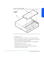
Page 117: ...ag being careful to grasp the disk module by its extraction handle see Figure 53 Fillers are not in ESD bags 4 Press the cam latch B toward the end of the extraction handle to loosen the extraction handle When you are installing a disk module filler align the disk filler guides with the chassis rails and insert the filler Push the filler in until it stops When it is fully inserted it will be flush...

Page 118: ...le as opposed to a filler monitor the LED D It should be on while the disk spins up and then turn off The LED will blink with I O activity to the disk If you observe different results refer to Chapter 4 Troubleshooting for probable causes 8 Run IOSCAN on the host and verify that the replacement disk module is claimed 9 Restore file systems and data as needed see Preparation HP UX 11 XX on page 110...

Page 119: ... this procedure Whenever possible follow ESD procedures Procedure Caution Do not remove a BCC from an operating product until you have the replacement BCC and are ready to install it An empty slot will cause uneven cooling and eventual overheating 1 Remove the cables and or terminators from the failed BCC 2 Loosen the locking thumbscrew A in Figure 54 until it clears the BCC bulkhead The screw sta...

Page 120: ...hes must have the same settings on both BCCs 7 Open the cam levers see Figure 54 of the replacement BCC by pulling them away from the center of the card 8 Insert the BCC in the empty slot 9 Push the cam levers flat against the center of the card to seat the BCC pins firmly on the midplane ...

Page 121: ...and a buzzer sounds the switch settings do not match the settings on the peer BCC For other solutions to a BCC fault see Isolating Causes in Chapter 4 11 Tighten the locking screws B in Figure 54 12 Reattach the SCSI cable and terminator Caution The BCC must be replaced or a filler panel installed in the open slot to ensure proper cooling for the disk system ...

Page 122: ... available the BCC slot must be filled to ensure proper cooling for the disk system This is done with a BCC filler panel For removal instructions for the BCC see page 119 Caution Do not remove the malfunctioning BCC until you have available either a BCC filler panel or a replacement BCC ...

Page 123: ...edures whenever possible Tools ESD wrist strap no hand tools are required to perform this procedure Whenever possible follow ESD procedures Procedure Caution Do not remove a power supply from an operating product until you have the replacement and are ready to install it An empty slot will cause uneven cooling and eventual overheating The power supply may be hot to touch 1 Disconnect the power cor...

Page 124: ...r supply the last 3 8 inch into the chassis and firmly seat the power supply on the midplane The power supply should be flush with the edge of the chassis 7 Tighten the thumbscrews on the power supply handles A and B It is recommended that you use a screwdriver to ensure proper seating 8 Plug the power cord into the power supply and electrical source 9 Monitor the power supply LED It should turn g...

Page 125: ...are Torx T25 screwdriver Torx T15 screwdriver Small flat blade screwdriver ESD wrist strap Whenever possible follow ESD procedures Procedure 1 Determine the file systems that will be inaccessible for I O operations while the disk system is turned off and perform necessary system administration See the HP UX guide How HP UX Works Concepts for the System Administrator 2 Push and release the power bu...

Page 126: ...proximately 54 pounds without disk modules installed 24 5 kg To avoid personal injury it is recommended that two people install the storage device in the rack 8 Push the disconnected disk system forward or lift it completely out of the rack as needed 9 When you are ready to replace the disk system push the chassis back into the rack ...

Page 127: ...screws 11 Reinstall the power supply fan module s 12 Reinstall the disk modules in the slots from which they were removed 13 Reconnect SCSI cables and power cords 14 Push the power button in to turn on the disk system 15 Perform necessary system administration to return file systems to service ...

Page 128: ...before removing the top cover 1 Remove disk modules and fillers and place them on an appropriate anti static surface See page 110 2 Disconnect all power and SCSI cables 3 Remove the power supply fan modules See page 123 4 Remove the disk system retention screws See page 126 5 Remove the disk system from the rack and place it on an appropriate anti static surface See page 125 Caution Removing the t...

Page 129: ... the middle of the chassis making sure to rotate the top cover down to align with the edges of the chassis 3 Insert the three Torx T10 screws through the holes as shown in Figure 59 4 Tighten the three Torx T10 screws 5 Reinstall the disk system in the rack See page 125 6 Reinstall the disk system retention screws to secure the disk system 7 Reinstall the power supply fan modules ...

Page 130: ...t be OFF out and the top cover removed in order to remove and replace the midplane board Caution Turning off a disk system isolates the enclosed disks from the host Perform recommended system administration to prevent loss of pending I Os to the disks Tools Small flat blade screwdriver Torx T25 screwdriver Torx T15 screwdriver Torx T10 screwdriver ESD strap Procedure 1 Remove the top cover See pag...

Page 131: ...ttom edges of the midplane see Figure 60 g Pull the midplane forward to clear alignment pins and lift it up and out of the disk system 4 To replace the midplane a Stand the new midplane inside the chassis and push it over the alignment pins Adjust the final position of the midplane as necessary for optimal connections to power supply fan modules BCCs and disk modules b Insert and tighten eight scr...

Page 132: ......

Page 133: ...the disk system 3 Disconnect the power cord s and SCSI cable s 4 Remove the power supplies and place them on an anti static surface 5 Remove the disk modules and carefully place them on an anti static surface Be sure to note the slots from which the disk modules were removed to replace them in the same slots Removing the deskside base and external covers from the disk system Tools Torx T25 driver ...

Page 134: ......

Page 135: ...Removal and Replacement 5 Rotate the disk system and place it on its top 6 Remove the four M5 screws from the array chassis using a Torx T25 driver They are the four screws that are closest to the center of the base See Figure 62 ...

Page 136: ...6 Removal and Replacement 7 Remove the four M5 screws from the cover using a Torx T25 driver They are the four screws that are closest to the edges of the base Figure 63 Base Removal from Chassis A base A ...

Page 137: ...Removal and Replacement 137 Removal and Replacement 8 Lift the disk system chassis off the alignment pins and out of the cover ...

Page 138: ...he disk system should be installed into the cover with the power switch down toward the closed part of the cover 3 Secure the base to the cover using four M5 screws Tighten the screws using a Torx T25 driver They are the four screws that are closest to the edges of the base 4 Secure the base to the chassis using four M5 screws Tighten the screws using a Torx T25 driver They are the four screws tha...

Page 139: ...slots should be facing up 6 Align the end cap tabs into the appropriate slots at the top of the disk system 7 Rotate the end cap down over the base aligning the small tabs at the top of the end cap with the end cap slots Insert and tighten the M5 retaining screws using the Torx T25 driver Be sure the retaining screw holes are aligned see Figure 67 ...

Page 140: ......

Page 141: ... models of the disk system are available A6490A and A6490AV field racked by HP qualified service engineers A6490AE empty field rack disk system A6490AD deskside disk system A6490ED empty deskside disk system A6490AZ factory racked disk system 6 ...

Page 142: ...15K rpm LVD disk module A6491A Bus Control Card C2362B 2 5 meter SCSI VHDTS68 HDTS68 M M Multimode Cable NT support only C2363B 10 meter SCSI VHDTS68 HDTS68 M M Multimode Cable NT support only C2365B 5 meter SCSI VHDTS68 HDTS68 M M Multimode Cable NT support only C2373A 2 meter VHDCI Ultra SCSI cable C2374A 5 meter VHDCI Ultra SCSI cable C2375A 10 meter VHDCI Ultra SCSI cable A6244A Rail kit for H...

Page 143: ...8 C13 outlets switch accessory E7682A 19 inch 200 240 V 30 Amp IEC 309 2 C19 8 C13 outlets switch accessory E4452A 36 inch 200 240 V 16 Amp L6 20P plug 6 IEC 320 outlets E4453A 36 inch 200 240 V 16 Amp L6 20P plug 6 IEC outlets E5933A 36 inch 110 240 V 16 Amp UPS IEC 320 6 IEC 320 outlets E4456A B 60 inch 220 V 16 Amp power cord w IEC 320 plug 6 IEC outlets E4457A B 60 inch 200 240 V 16 Amp L6 20P...

Page 144: ...250 69001 Power supply Fan module A6490 67005 Midplane Assembly A6491 67001 A6491 69001 Bus Control Card BCC A6490 67002 BCC Filler Panel A6198 67002 Disk Filler Panel A6537 67001 A6537 69001 18 GB 10k rpm LVD disk module A6538 67001 A6538 69001 36 GB 10k rpm LVD disk module A6539 67001 A6539 69001 73 GB 10k rpm LVD disk module A6540 67001 A6540 69001 18 GB 15k rpm LVD disk module A6541 67001 A654...

Page 145: ...tion The maximum dimensions of the deskside version are Height 49 1 cm 19 3 in Width 31 7 base cm 12 5 in Depth 60 7 cm 23 9 in Weight 37 3 46 4 kg 82 102 lbs depending on configuration Weight A fully loaded disk system weighs approximately 77 pounds Component weights are shown in Table 17 Table 17 Product Weights Component Weight of Each lbs Quantity Subtotal lbs Disk Module LP 1 6 14 22 4 Power ...

Page 146: ...ducts are retested under the same conditions However the limits of these specifications do not represent the optimum for long trouble free operation and specifically are not recommended for maximum satisfaction The recommended conditions are stated when appropriate Operating temperature 5º C to 38º C 41º F to 100º F Recommended 20º C to 25 5º C 68º F to 78º F Storage temperature 40º C to 70º C 40º...

Page 147: ...nd power 6 7 Bels Sound pressure at operator s position 51 6 dB A Safety Certifications UL listed UL 1950 1995 3rd Edition CSA certified C22 2 No 950 1989 TUV certified with GS mark EN 60950 1992 A1 1993 A2 1993 A3 1995 A4 1997 CE mark see G Declaration of Conformity on page 151 EMC Compliance Australia AS NZS 3548 Class A Canada ICES 003 Class A China CB9254 88 European Union EN55022 Class A EN50...

Page 148: ...pment in a residential area is likely to cause harmful interference in which case the user will be required to correct the interference at his own expense The end user of this product should be aware that any changes or modifications made to this equipment without the approval of Hewlett Packard could result in the product not meeting the Class A limits in which case the FCC could void the user s ...

Page 149: ...artement du lieu d exploitation Le formulaire à utiliser est disponible auprès des préfectures La déclaration doit être faite dans les 30 jours suivant la mise en exploitation Le non respect de cette obligation peut être sanctionné par les peines prévues au code des Postes et Télécommunications et celles indiquées dans la loi du 31 mai 1993 susvisée Arrêté du 27 Mars 1993 publié au J O du 28 Mars ...

Page 150: ...150 Reference E VCCI Statement Japan Harmonics Conformance Japan F BCIQ EMC Statement Taiwan ...

Page 151: ...Reference 151 Reference G Declaration of Conformity ...

Page 152: ...cuments The following manuals explain how to use the system software interfaces to the StorageWorks Disk System 2300 EMS Hardware Monitors User s Guide available at http www docs hp com hpux systems Online Diagnostics for HP 9000 Support Tools Manager Overview available at http www docs hp com hpux systems HP UX System Administration Tasks Manual HP Order No B2355 90079 ...

Page 153: ...C filler panel description of 19 Bus Reset Hot Swap switch 85 Bus Reset Pwr Fail switch 85 C cables See SCSI cables or power cables Cautions damage to power switch 128 data loss 130 multiple disk systems 70 operating with empty slot 119 123 permanent BCC damage 119 permanent disk damage 117 119 removing disk module 116 top cover 128 turning off the disk system 130 CommandView SDM 100 configuration...

Page 154: ...al services event notification 97 environmental services features of 17 event messages contents of 98 event monitor 97 EMS 17 setting up 90 user guide 152 event notification 90 97 99 exchange part numbers 144 F fan troubleshooting 106 firmware mismatch 104 obtaining latest release 91 troubleshooting 106 updating 91 FRUs JBOD enclosure part num bers 109 Full Bus switch 85 H hardware requirements 24...

Page 155: ...111 LVD definition 33 LVD terminator order number 44 M midplane installing 130 removing 130 model numbers 141 O operating systems supported 24 order number BCC 44 LVD terminator 44 PDU PDRU 143 upgrade products 142 User Guide 44 P part numbers 144 JBOD enclosure FRUs 109 PDU PDRU definition 33 installing 39 order numbers 143 troubleshooting 104 physical volume group 111 physical volumes attached 1...

Page 156: ... cover 128 disk filler 115 disk module 115 midplane 130 power supply fan module 123 replaceable parts descriptions of 18 23 replacement part numbers 144 restoring operation 125 S safety certifications 147 SCSI cable installing 75 products 142 site preparation 36 electrical 36 PDU PDRU 37 software requirements 24 verifying 42 status LEDs 101 102 steady state current 36 STM user guide 152 switch set...

Page 157: ...system 80 U Ultra 3 SCSI definition 34 upgrade products order numbers 142 User Guide order number 44 V verify connection to the host 81 voltage troubleshooting 106 volume groups 111 W web site documents 152 weight product 145 ...

Page 158: ...158 ...

Reviews: