background image

1-14 

Product Information 

Technology Code IC) 

Internal Design 

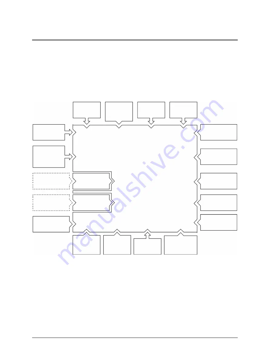
The motherboard PCA is the central component of the notebook’s design, and plays a role in virtually 
all system functions. The CPU module and most other subsystems connect to the motherboard. 

The following figure shows the electrical connections among the notebook’s replaceable electronic 
modules. In addition, the table on page 1-15 lists the roles that the replaceable modules play in each of 
the notebook’s functional subsystems. 


Figure 1-8. Replaceable Module Diagram 

Motherboard PCA 

Mini-PCI card 

CD/DVD drive 

Battery 

Keyboard 

PCMCIA 

socket 

PCMCIA card 

Top case


touch/scroll pads, 

click buttons, CD 

player, IR (optional)


CPU module 

Keyboard 

cover switch 

PCA 

Display 

assembly 

Speakers 

SDRAM modules 

Volume control 

PCA 

Hard disk drive 

Fan 

Bluetooth 

PCA 

USB PCA 

SD-MMC card 

SD-MMC 

socket 

Audio PCA 

Summary of Contents for Pavilion XZ200 Series

Page 1: ... HP Pavilion zt1100 xz200 Omnibook xt1500 For use with Technology Code IC Service Manual ...

Page 2: ...Thank you for purchasing this Factory Service Manual CD DVD from servicemanuals4u com Please check out our eBay auctions for more great deals on Factory Service Manuals servicemanuals4u ...

Page 3: ...hose programs without prior written permission of Hewlett Packard Co is also prohibited Portions of the programs that control this product may also be copyrighted by Microsoft Corporation SystemSoft Corp Insyde Software Corporation S3 Graphics Incorporated and Adobe Systems Incorporated See the individual programs for additional copyright notices This product incorporates copyright protection tech...

Page 4: ...g the Mini PCI Card HP Authorized Service Providers Only 2 16 Removing the Display Assembly HP Authorized Service Providers Only 2 18 Removing Display Assembly Components HP Authorized Service Providers Only 2 20 Removing the Fan and Heatsink HP Authorized Service Providers Only 2 22 Removing the CPU Module HP Authorized Service Providers Only 2 25 Removing the Top Case HP Authorized Service Provi...

Page 5: ...ure 2 9 Disconnecting the Keyboard 2 12 Figure 2 10 Removing an Expansion SDRAM Module 2 13 Figure 2 11 Installing an Expansion SDRAM Module 2 14 Figure 2 12 Removing the System SDRAM Module 2 14 Figure 2 13 Removing the Mini PCI Card 2 17 Figure 2 14 Removing the Display 1 2 18 Figure 2 15 Removing the Display 2 2 19 Figure 2 16 Removing Display Assembly Components 2 21 Figure 2 17 Removing the F...

Page 6: ...2 1 Table 2 2 Required Equipment 2 3 Table 2 3 Recommended Screw Torques 2 3 Table 2 4 Replacing Small Parts User Replaceable 2 15 Table 2 5 Removing Notebook Components 2 37 Table 3 1 Scope of Diagnostic Tools 3 5 Table 3 2 Troubleshooting Suggestions 3 5 Table 3 3 Insyde MobilePRO BIOS POST Beep Codes and Messages 3 25 Table 3 4 Sycard PCCtest Commands 3 26 Table 3 5 BIOS Configuration Menus and...

Page 7: ...te http www hp com notebooks European mirror http www europe hp com notebooks HP Business Support web Site www hp com go bizsupport HP Partnership web site http partner americas hp com Restricted to Authorized Resellers only HP Asia Pacific Channel Support Centre for DPSP Partners http www hp com au Restricted to DPSP Partners only HP MCD web site http www mcd hp com HP s internal web site for div...

Page 8: ...DR Combo Yes 56K LAN F3400H xz295 P4 1 6 GHz 15 0 in TFT XGA 30 GB 512 MB DDR 2 x 256 Combo Yes 56K LAN F3437H zt1172 P4 1 4 GHz 14 1 in TFT XGA 20 GB 256 MB DDR Combo Yes 56K LAN F3438H zt1182 P4 1 4 GHz 15 0 in TFT XGA 20 GB 256 MB DDR Combo Yes 56K LAN F3439H zt1192 P4 1 5 GHz 15 0 in TFT XGA 30 GB 256 MB DDR Combo Yes 56K LAN Omnibook xt1500 F3444H xt1500 P4 1 4 GHz 14 1 TFT XGA 20 GB 256 MB D...

Page 9: ...rences where applicable The table below shows the technology codes and the changes they signify for the products Before downloading software or drivers or performing repairs note the technology code for the HP notebook model Note that the first two characters of the BIOS ID for example IC M1 02 indicate the hardware technology You can also determine the BIOS ID using the BIOS configuration utility...

Page 10: ...mable 2 Power button 3 Keyboard status lights Caps Lock Num Lock CD or DVD drive activity 4 Touch pad scroll pad on off button with on off indicators on either side 5 Left and right click buttons 6 Touch pad 7 Scroll pad 8 Volume controls selected models 9 Mute button and indicator light selected models 10 Removable DVD or DVD CD RW drive 11 CD DVD eject button 12 Speaker one on each side 13 Latch...

Page 11: ...USB ports 2 19 S video TV out port colored yellow 20 Reset switch 21 Kensington lock slot security connector 22 LAN port and indicators 23 Modem 24 IEEE 1394 connector 25 SD MMC Card slot 26 PC Card slot Type II 27 PC Card eject button 28 Hard disk drive 29 Wireless on off button and indicator light selected models 30 External microphone jack colored pink 31 Headphones jack colored green ...

Page 12: ... IC Product Information 1 5 Figure 1 3 Bottom View 32 Infrared port selected models 33 Battery 34 CD DVD drive latch 35 RAM cover 36 Battery latch 37 Docking port 38 Mini PCI cover 39 Hard disk drive retaining screws ...

Page 13: ...play and other components Saves significant power Restarts quickly Restores network connections Power mode status light is amber Click Start Turn Off Computer Stand By or press the power button or allow timeout Press the power button to quickly resume your session Hibernation Saves current session to disk then turns off Saves maximum power Restores network connections Power mode status light is of...

Page 14: ...s accessing the hard disk drive 2 Power mode Green the notebook is on even if the display is off Amber the notebook is on standby Off the notebook is off or in hibernation 3 Battery charge status Green the AC adapter is connected and the battery is fully charged Amber the AC adapter is connected and the battery is charging Red the AC adapter is connected and the battery has a fault Off the AC adap...

Page 15: ... keys Table 1 3 Fn Hot Keys Hot Key Effect Fn F1 Decreases the display brightness Fn F2 Increases the display brightness Fn F5 Toggles among the built in display an external display and simultaneous display on both Fn F8 Toggles the built in numeric keypad on and off Does not affect an external keyboard If Num Lock is on the numeric functions are active otherwise cursor control is active Fn Num Lo...

Page 16: ...Ctrl Alt Del then click Shut Down Press and hold the power button for about four seconds until the display turns off Use a pen or straightened paper clip to press the reset switch on the back of the notebook Figure 1 6 Resetting the Notebook Press the power button to turn the notebook on again Note To boot from a CD or DVD insert a bootable CD such as the Recovery CDs into the drive then restart P...

Page 17: ...n the notebook is on the volume control buttons also govern the volume for most audio applications If the notebook is off on standby or in hibernation slide the multimedia power switch to the left to activate the player For details about using the CD DVD player see the notebook s Reference Guide Figure 1 7 Multimedia Buttons and Status Panel 1 MP3 player launch button 2 Previous track button 3 Nex...

Page 18: ...r supports MPEG2 overlay Supports simultaneous LCD CRT operation same image on both displays Integrated VGA Up to 32 MB video memory shared with system memory Supports NTSC and PAL TV Dual display for LCD and external monitor or TV External color support starting at 640 x 480 up to 1600 x 1200 display resolution Power Rechargeable 8 cell Lilon battery 14 8 V 3900 mAH Battery life up to 2 5 hours v...

Page 19: ...ack One headphone out jack Expandability One Type II 16 32 bit PC Card slot 3 3 and 5 V support CardBus enabled One integrated Secure Digital Multi Media Card slot Optional simple port replicator selected models Security Features User and administrator passwords DMI accessible electronic serial number Kensington MicroSaver lock slot Environmental Limits Operating temperature 0 to 40 C 32 to 104 F ...

Page 20: ...ive Case F1645A Kensington Lock F1747A Defcon Lock F1771A Universal Carrying Case F1778A Promotional Carrying Case NAM AP F1778B Standard Carrying Case Europe Only F2020A Executive Leather Case Europe only F2100A F4815A USB Optical Mouse F2135C Wireless Comm Access Point F2136B Wireless PC Card 128 bits F2196A F4862A 3Com Bluetooth PC Card F2297A Car Adapter 24 V EU only F4496A 512 MB PC2100 DDR S...

Page 21: ... replaceable electronic modules In addition the table on page 1 15 lists the roles that the replaceable modules play in each of the notebook s functional subsystems Figure 1 8 Replaceable Module Diagram Motherboard PCA Mini PCI card CD DVD drive Battery Keyboard PCMCIA socket PCMCIA card Top case touch scroll pads click buttons CD player IR optional CPU module Keyboard cover switch PCA Display ass...

Page 22: ... player PCA Keyboard controller keyboard BIOS Key switches One Touch buttons CD player buttons Touch pad Motherboard Top case Keyboard BIOS Touch scroll pad sensors click buttons Audio Motherboard Display assembly USB PCA Volume control PCA Speakers Audio controller audio decoder speaker amplifier external microphone jack Microphone Headphone jack Volume control Sound output Status Motherboard Top...

Page 23: ......

Page 24: ...1 Module CPU page 2 25 Module plug in page 2 5 Module expansion SDRAM page 2 13 Module system SDRAM page 2 14 PCA audio page 2 37 PCA inverter page 2 20 PCA motherboard page 2 32 PCA volume control page 2 39 Saddles hinge page 2 30 Socket PCMCIA page 2 39 Speaker left page 2 39 Speaker right page 2 39 Tray hard disk drive page 2 7 Caution Always provide proper grounding when performing repairs Wit...

Page 25: ...r secondary SDRAM module mini PCI card hard disk drive DVD CD RW drive Keyboard cover Keyboard B Left speaker Right speaker Docking doors PCMCIA doors PCMCIA socket A Display assy Heatsink CPU module Modules on path A If removing motherboard or bottom case modules on path B Top case Hinge saddles Motherboard or bottom case Audio PCA Volume control PCA CD player PCA Infrared PCA Hard disk drive gui...

Page 26: ... 2 2 Required Equipment 0 Phillips screwdriver preferably magnetized Small flat blade screwdriver 5 mm hex driver Table 2 3 Recommended Screw Torques Screw Thread Size Torque cm kgf Torque in lbf M2 5 2 11 mm long 3 0 3 5 2 6 3 0 M3 3 0 3 5 2 6 3 0 NOTES ...

Page 27: ...oval Procedure Slide the battery s release latch in the direction of the arrow on the latch then lift the battery out of its compartment Figure 2 2 Removing the Battery Reassembly Notes Insert the front end of the battery into the battery compartment then press the back end in until the battery clicks into place ...

Page 28: ...cement 2 5 Removing a Plug In Module User Replaceable Required Equipment None Removal Procedure Slide the module release latch in the direction shown by the arrow on the latch and remove the module Figure 2 3 Releasing the Plug in Module ...

Page 29: ...Procedure 1 Unplug the AC adapter if present and remove the battery 2 On the bottom of the unit remove both hard drive retaining screws Figure 2 4 Removing the Hard Disk Drive 3 Carefully pull the hard drive out of the notebook 4 Remove all four screws from the hard drive tray and drive case then lift the drive out of the tray Screws M2 5 4mm ...

Page 30: ...ower the drive into place Carefully slide the hard drive assembly into its compartment Press firmly to make sure the connector seats properly Important If you are installing a new hard disk drive install the factory software and operating system on the drive before loading any additional software see Recovering and Reinstalling Software below Screws M2 5x4mm 2 Screws M2 5x4mm 2 ...

Page 31: ... not interrupt the following process or unplug the AC adapter until the process is complete 1 Back up all data from the hard disk 2 Connect the AC adapter to the notebook This is necessary to provide an uninterrupted power source the notebook s battery alone is not adequate 3 Insert Recovery CD disk 1 into the notebook s CD DVD drive If the notebook is turned off use a pin or straightened paper cl...

Page 32: ...igure 2 6 Removing the Keyboard Cover Retaining Screws 3 Open the display so that it lays flat 4 Use the flat blade screwdriver to carefully pry up the right end of the keyboard cover just above the Page Up key then lift the end until the cover unsnaps Caution When removing the keyboard cover be careful not to pull on the cable that connects the keyboard cover to the notebook 5 Carefully lift the ...

Page 33: ...k Figure 2 7 Removing the Keyboard Cover Reassembly Notes Make sure the keyboard cover switch cable is securely connected to the motherboard Bend the center of the keyboard cover upward slightly and insert the tabs on the ends of the cover into the slots in the notebook s case Fit the hinge covers over the hinges and gently press the cover into place ...

Page 34: ...sen the three retaining screws along the top of the keyboard the keyboard may retain the screws Figure 2 8 Loosening the Keyboard Retaining Screws Caution When opening the keyboard be careful not to pull on the ribbon cable that connects the keyboard to the notebook 4 Raise the top of the keyboard then lift the keyboard up and out of the notebook 5 Lay the keyboard face down on the top case forwar...

Page 35: ...They could be very hot if the notebook was running recently Figure 2 9 Disconnecting the Keyboard Reassembly Notes Lay the keyboard face down on the top case forward of its normal position and reconnect the ribbon cable Slip the metal tabs on the bottom of the keyboard into their slots in the top case then lower the keyboard into place ...

Page 36: ... SDRAM module only by its edges or you could damage the module through electrostatic discharge Required Equipment 0 Phillips screwdriver Removing an Expansion SDRAM Module Removal Procedure 1 Unplug the AC adapter if present and remove the battery 2 On the bottom of the notebook loosen the screw holding the SDRAM cover the cover retains the screws and remove the cover 3 Press outward to release th...

Page 37: ...er if present and remove the battery 2 Remove the keyboard cover page 2 9 3 Open the keyboard page 2 11 steps 1 though 4 You don t need to disconnect the keyboard cable 4 Press outward to release the latches at the sides of the SDRAM module so that the free edge of the module pops up then pull the module out of the connector Figure 2 12 Removing the System SDRAM Module Reassembly Notes Carefully p...

Page 38: ...cover Cover expansion SDRAM Included in door kit F3377 60933 On the bottom of the notebook loosen the screw in the SDRAM module cover the cover retains the screw and remove the cover Covers screw on display bezel Included in feet cover kit F3377 60967 Insert a small flat blade screwdriver under the cover and pry it loose To replace firmly press the adhesive side of the cover into the recess Feet r...

Page 39: ...s edges or you could damage it through electrostatic discharge Required Equipment 0 Phillips screwdriver Removal Procedure 1 Unplug the AC adapter if present and remove the battery 2 On the bottom of the notebook loosen the screw holding the mini PCI cover the cover may retain the screw and remove the cover 3 Press outward to release the latches at the sides of the card and carefully lift its free...

Page 40: ...g the Mini PCI Card Reassembly Notes Reattach the cable s to the card and tuck them into the compartment Gently press the card into the connector at an angle of about 30 until it is fully inserted Then press down on both sides of the card until the latches snap closed ...

Page 41: ...e Display 1 4 Open the display so that it lays flat 5 Remove the screw from the left speaker and move the speaker to the side Be careful not to pull on the wires connecting the speaker to the motherboard 6 Disconnect the display cable and ground wire from the motherboard and carefully remove the cable from the retaining clip near the left display hinge 7 If present disconnect the wireless cables n...

Page 42: ...t remains approximately flat Make sure the cable fits into its slot in the bottom case and reinsert the cable into the retaining clip near the left display hinge Make sure the tabs on the left side of the left speaker fit between the corresponding tabs in the bottom case and the speaker wires fit through their notch in the bottom case Screw M2 4mm Screws M2 4mm 3 ...

Page 43: ...al assemblies Keyboard cover page 2 9 Display assembly page 2 18 3 Use a screwdriver or similar object to carefully pry the screw covers from the display bezel 4 Remove the four screws from the display bezel 5 Beginning at the top center of the display carefully pry up the inner edge of the bezel with thumbs and fingers Work your way around the inside edge to unsnap the latches then remove the bez...

Page 44: ...ole in the wireless antenna fits over the corresponding post in the display case Set the bezel in place on the display then work your way around the bezel firmly snapping the bezel latches shut The rounded screw co vers go on the screws at the top of the display bezel and the flat covers go on the screws at the bottom of the bezel Screw M2 4mm Screws M2 4mm 2 Screws M2 4mm 2 Screws M2 5x6mm 4 Inve...

Page 45: ...2 9 Keyboard page 2 11 3 Remove the retaining screw from the right speaker Disconnect the speaker wires from the motherboard and lift the speaker out of the notebook 4 Disconnect the fan wires from the motherboard 5 Remove both retaining screws from the fan 6 Lift the fan out of the notebook Caution Do not spin the fan blades with your finger or you could damage the fan s bearings 7 Remove the hea...

Page 46: ...nd Replacement 2 23 Figure 2 17 Removing the Fan and Heatsink Caution Be careful not to touch the upper surface of the CPU module or you could damage it Screws M2 4mm 2 Screw M2 5x6mm Screws heatsink with springs 4 Screw M2 5x8mm ...

Page 47: ...n or beneath the cooling fins Insert the cooling fins into the opening in the bottom case then set the heatsink onto its standoffs Tighten the heatsink screws in the order indicated by the numbers on the heatsink Make sure the upper surface of the heatsink is clean and install a new thermal pad Be careful not to scratch the upper surface of the pad and make sure the pad lies flat on the heatsink F...

Page 48: ...e it 1 Unplug the AC adapter if present and remove the battery 2 Remove these additional assemblies Keyboard cover page 2 9 Keyboard page 2 11 Fan and heatsink page 2 22 3 Carefully insert the tip of a flat blade screwdriver in the CPU module lock mechanism and turn the screwdriver a few degrees counterclockwise until the mechanism clicks into its OPEN position The CPU socket moves slightly to the...

Page 49: ...ket Make sure the module is fully seated and that none of its pins are bent or otherwise damaged Carefully insert the tip of the flat blade screwdriver in the CPU module lock mechanism and turn the screwdriver a few degrees clockwise until the mechanism clicks into its LOCK position The CPU socket moves slightly to the right when this happens ...

Page 50: ...ional assemblies Plug in module page 2 5 Hard disk drive page 2 6 Keyboard cover page 2 9 Keyboard page 2 11 Display assembly page 2 18 3 Remove the retaining screws from the bottom of the notebook 4 Remove the screws from just inside the hard disk drive compartment and just inside the plug in module compartment Figure 2 20 Removing the Top Case Retaining Screws Screws M2 4mm 2 Screw M2 4mm Screws...

Page 51: ...ht speaker disconnect its wires from the motherboard and lift the speaker out of the notebook 9 Raise the back of the top case then gradually loosen it moving around the edges of the case toward the front of the notebook Caution When removing the top case be careful not to pull on the cable that connects the CD player PCA in the top case to the notebook 10 Carefully lift the top case forward and o...

Page 52: ...he touch pad cable and CD DVD player PCA cable and volume PCA cable if present are securely connected If present reinsert the wireless cables into their slot in the top case Make sure the tabs along the edges of the case snap shut Screws M2 4mm 2 Screws M2 5x6mm 2 Screws M2 4mm 3 Screws M2 4mm 3 Screws M2 4mm 5 ...

Page 53: ...page 2 11 Display assembly page 2 18 Top case page 2 27 3 Remove the retaining screws from the right hinge saddle and lift the hinge saddle out of the notebook 4 Remove the retaining screws from the left hinge saddle and lift the hinge saddle out of the notebook Caution Be careful not to damage the volume control PCA if present after removing the right hinge saddle If excessive handling of the bot...

Page 54: ...dles Reassembly Notes Make sure the posts on the underside of the hinge saddles line up with the openings in the bottom case and that the holes in the front ends of the saddle fit over the alignment posts in the bottom case Screw M2 4mm Screws M2 5x6mm 3 Screw M2 5x6mm Screw M2 5x8mm ...

Page 55: ...the prompt Otherwise copy hp drivers hputils ESN EXE from the Recovery CD then run it on the notebook 3 Store the serial number and service ID as directed Removal Procedure 1 Unplug the AC adapter if present and remove the battery 2 Remove these additional assemblies Battery page 2 4 Plug in module page 2 5 Hard disk drive page 2 6 Keyboard cover page 2 9 Keyboard page 2 11 SDRAM modules page 2 13...

Page 56: ...the front edge of the motherboard slightly then carefully lift the motherboard forward and out of the bottom case Figure 2 23 Removing the Motherboard Reassembly Procedure When reinstalling the motherboard see Reinstalling the Motherboard on page 2 34 When reinstalling the bottom case see Replacing the Bottom Case on page 2 35 Screws M2 4mm 2 Screws M2 5x6mm 3 Screws M2 5x6mm 2 Screw M2 5x6mm Scre...

Page 57: ...you must electronically transfer to it the serial number and service ID from the previous motherboard 1 Exit Windows and boot to a DOS prompt 2 Run ESN EXE from the same source you used when saving the serial number and service ID from the previous motherboard On a factory software installation change to the hp drivers hputils directory and type esn at the prompt Otherwise copy hp drivers hputils ...

Page 58: ...uct ID label 2 Transfer the old serial number label and install a new overlay or create a new serial number label using the steps on the following page 3 If you need to install or replace the docking doors or PCMCIA doors refer to the figures below Figure 2 24 Installing the Docking Doors Figure 2 25 Installing the PCMCIA Doors ...

Page 59: ...cturing location 1 Open a new document based on the serial label template 2 Enter the information from the old serial label and print the new label on plain white paper The new label does not have barcodes 3 Carefully cut out the new serial label just inside the border and place it into the inner recess in the bottom case The bottom of the label goes toward the front of the case 4 While holding th...

Page 60: ...omponents Component Removal Procedure Additional Steps Antenna wireless See page 2 20 Bezel display See page 2 20 Card mini PCI See page 2 16 Case bottom See page 2 32 Case top See page 2 27 Cover keyboard See page 2 9 Display assembly See page 2 18 Doors docking Plug in module page 2 5 Hard disk drive page 2 6 Keyboard cover page 2 9 Keyboard page 2 11 SDRAM modules page 2 13 Mini PCI card page 2...

Page 61: ... of the motherboard Guides optical disk drive Keyboard cover page 2 9 Keyboard page 2 11 Display assembly page 2 18 Top case page 2 27 Remove the retaining screw on each guide and lift the guides off of the motherboard Heatsink See page 2 22 Keyboard See page 2 11 Module CPU See page 2 25 PCA Audio Keyboard cover page 2 9 Keyboard page 2 11 Display assembly page 2 18 Top case page 2 27 Hinge saddl...

Page 62: ...es hinge See page 2 30 Socket PCMCIA Plug in module page 2 5 Hard disk drive page 2 6 Keyboard cover page 2 9 Keyboard page 2 11 SDRAM modules page 2 13 Mini PCI card page 2 16 Display assembly page 2 18 Fan and heatsink page 2 22 CPU module page 2 25 Top case page 2 27 Hinge saddles page 2 30 Motherboard page 2 32 Remove the four screws M2x3 5 attaching the PCMCIA socket to the motherboard and re...

Page 63: ......

Page 64: ...f the notebook and for identifying faulty components Troubleshooting information Checking for customer abuse page 3 3 Troubleshooting the problem page 3 4 Verifying the repair page 3 4 Suggestions for troubleshooting page 3 5 Diagnostic tools e Diagtools diagnostic program page 3 22 Power on self test page 3 25 Sycard PCCtest 450 PC Card page 3 26 BIOS configuration utility page 3 27 ...

Page 65: ...s follow the basic troubleshooting steps shown below Check the customer s description of the problem and any supporting information Try to duplicate the customer s problem Troubleshoot the problem using Diagnostic tools Troubleshooting suggestions Verify the repair by testing the functionality of the complete unit Check for customer abuse Figure 3 1 Basic Troubleshooting Steps ...

Page 66: ...ot be declared If the damage could have a cause other than customer abuse customer abuse cannot be declared If the unit shows any of the following customer abuse is declared Missing parts Broken plastic parts Parts not original to the unit Damaged or missing keys on the keyboard Table 3 2 on page 3 5 includes additional criteria for determining customer abuse to specific parts of the unit Importan...

Page 67: ...rd PCCtest Table 3 1 on page 3 5 shows how you can use these tools to isolate the cause of the notebook s problem The troubleshooting suggestions on page 3 5 include general suggestions for repairing units that show specific failure symptoms Swapping modules that may be defective with others known to be good is generally an ideal way to find the module responsible for the problem A failure symptom...

Page 68: ... to help find the problem Table 3 2 Troubleshooting Suggestions Symptom Call Center Suggestions Repair Center Likely Causes Repair Center Comments To help determine likely causes check to see what replaceable modules are involved in the system function and what roles they play See Figure 1 8 on page 1 14 and Table 1 6 on page 1 15 Startup Does not boot on battery but boots on AC Make sure battery ...

Page 69: ... module then motherboard If OS starts from floppy drive use Recovery CDs to reinstall factory software onto hard drive replace hard drive Beeps once spins hard disk repeats but does not boot SDRAM module Make sure at least one SDRAM module is installed Error message such as Invalid system disk or Auto IDE error Check for disk in floppy drive Check boot order using BIOS configuration utility Remove...

Page 70: ...book press F6 when HP logo appears and follow onscreen instructions This calibrates the battery and requires four to five hours You cannot use notebook during this process Certain applications can cause excess CPU and power usage Users can get Intel Power Monitor from www intel com and monitor CPU load When playing DVD movies on battery power use Power Options in Control Panel to select Portable L...

Page 71: ...rs uninstall that software Contact software vendor for additional support Notebook resumes slowly from standby Notebook can take a minute or longer to resume if network card is installed Blinking cursor appears while system is loading and checking hardware and network connections When hardware is reinitialized Windows desktop appears Does not go on standby as expected The notebook won t suspend if...

Page 72: ...e quality statement on page 5 2 Display cable connection Display assembly Check display cable connection See quality statement on page 5 2 Punctured display Declared to be caused by customer abuse Vertical crack near center of display Usually caused by closing display with pencil sized object on keyboard Declared to be caused by customer abuse Scratched display glass Declared to be caused by custo...

Page 73: ...as a monitor Notebook s S video TV out port is optimized for DVD display Performance may vary when using S video port for other applications Before using TV set as monitor switch notebook s display resolution to 800 by 600 pixels 1 Connect video cable from TV set to notebook s S video port 2 Turn on TV 3 Click Start Control Panel Appearance and Themes Display Settings then click Advanced button 4 ...

Page 74: ...uded hard disk capacity reported by Windows CD DVD drive Particular CD or DVD not playing properly Check disk for proper insertion dirt or damage Clean with soft cloth or replace as needed If CD was created on CD RW drive try using HP certified media Read and write quality may vary for other media Cannot read any CD or DVD Restart the notebook Make sure the CD DVD drive is inserted properly CD DVD...

Page 75: ...et resolution or color depth before starting DVD player You cannot change these once DVD player is started Some combinations of color depth and resolution not supported in DVD playback If needed reduce color depth or display resolution No DVD or CD RW software on notebook CD DVD drive module may not have been properly installed first time notebook was booted Make sure drive is correctly installed ...

Page 76: ...after adding SDRAM Use only PC133 or higher SDRAM modules SDRAM module Audio No sound is audible Increase sound volume Make sure sound is enabled software controls Check for sound resource conflicts in Device Manager Sound may not operate properly in MS DOS mode Check speaker cable connections Speakers Motherboard Check operation using headphones or external speakers Built in microphone does not r...

Page 77: ...ke sure floppy drive is connected correctly Use BIOS configuration utility to check boot order Floppy drive Motherboard Modem Modem will not connect at 56K Verify that host modem supports 56K V 90 connection speed Try connecting later in case line quality or other external factor is cause of problem Modem doesn t dial or no dial tone Check all cables and connections Connect a standard telephone to...

Page 78: ... Try disabling error correction and data compression Download latest modem driver from technical support area of HP notebook web site see page vi Mini PCI card Motherboard Modem dials incorrectly Check number you entered including digits required for outside access or long distance Check dialing options in Control Panel look for duplicate digits for outside access or long distance In foreign count...

Page 79: ...ams If faxing by printing from application make sure fax printer is selected Turn off power management features temporarily General problems If PC card modem is not working disable internal modem in Control Panel Download latest modem driver from technical support area of HP Notebook web site see page vi Mini PCI card Motherboard One Touch button problems Buttons not working properly Make sure cor...

Page 80: ...er device Use networking troubleshooter in Windows Help Make sure LAN cable is Category 3 4 or 5 for 10Base T operation or Category 5 for 100Base TX operation Maximum cable length is 100 m 330 ft Mini PCI card Motherboard Can t browse My Network Places Check with network administrator to make sure network supports NetBEUI protocol Use Windows Search to locate computer on network Can t log in to Ne...

Page 81: ...s of infrared radiation can cause transmission errors Make sure only one application is using infrared port Remove any PC Cards from notebook possible IRQ conflict For fast IrDA check for DMA conflict with ECP parallel port Motherboard Wireless General problems Check TCP IP setup in Control Panel Check SSID and channel settings click wireless link icon in taskbar and select Advanced Configuration ...

Page 82: ...ace motherboard If only one slot has a problem try replacing PCMCIA socket Data loss Stop PC card before removing it to avoid data loss PC card modem not working Disable internal modem Video file playback AVI or MPEG file doesn t play with two displays Before playing press Fn F5 to switch to one display Cannot switch displays after play begins If using both displays video image will not appear on ...

Page 83: ...g software can affect performance Press Ctrl Alt Del to see if an application is not responding Restart notebook If hard disk has spun down to conserve power it can take several seconds to spin up If needed use Power Options in Control Panels to change hard disk time out to match standby time out Some file browsers respond slowly while processing graphics or waiting for broken network connections ...

Page 84: ...tebook on a flat surface so air can flow freely around and underneath Make sure air vents are clear Check fan and heatsink installation Games and other programs that drive CPU usage toward 100 can contribute as can charging battery Fan Heatsink Check fan and heatsink for proper operation or damage Clock loses time Plug in AC adapter for 24 hours to charge CMOS battery Motherboard ...

Page 85: ...am provides two levels of testing Basic user level hardware test Advanced individual hardware tests Figure 3 2 e Diagtools Screens Basic and Advanced The tests are designed to run after the system restarts so that the notebook will be in a predictable state during the tests The tests are non destructive and are intended to preserve the state of the notebook The notebook restarts when you exit the ...

Page 86: ...ptional Run the advanced tests Press F2 to open the advanced test screen 10 Select and run the appropriate tests Note that individual tests do not appear if the hardware they test is not detected Press the following keys to run tests Enter Runs the highlighted test F5 or Space Marks unmarks the highlighted test F6 Marks unmarks all tests in the current menu F7 Marks unmarks all tests in all menus ...

Page 87: ... before running the test See the wiring diagrams below 14 1 25 13 Figure 3 3 Parallel Loopback Connector Interpreting the Results The e Diagtools diagnostic program returns test groups error codes and suggestions for repair and or follow up actions Consider these suggestions in combination with other troubleshooting information in servicing the notebook ...

Page 88: ...a terminal error beep code and or displaying a message see the following table The beep code indicates the POST routine in which the terminal error occurred If the system fails after you make changes using the BIOS configuration utility reset the notebook enter the BIOS configuration utility and install the defaults or correct the error Table 3 3 Insyde MobilePRO BIOS POST Beep Codes and Messages ...

Page 89: ...pend to Disk partition size TOO SMALL Suspend to Disk partition has insufficient capacity None MEMORY SIZE HAS CHANGED REBOOTING Memory size has changed after previous Suspend to Disk operation Sycard PCCtest 450 460 CardBus Card Optional The PCCtest 450 and 460 CardBus Cards version 1 05 available from Sycard Technology are the only recommended diagnostic tool that tests the functionality of the ...

Page 90: ...xit menu to exit the utility Table 3 5 BIOS Configuration Menus and Parameters Pavilion zt1100 xz200 and Omnibook xt1500 Settings for BIOS version IB M1 00 Spring 2002 Startup Menu Description Default Date and Time Sets the date using mm dd yyyy format and the time using 24 hour format Values set take effect immediately Boot Device Shows the order of boot devices with indicating a device category ...

Page 91: ... first Also sets whether the password is required when the notebook boots or to enter the BIOS configuration utility Enter Exit Menu Description Save and Reboot Saves changes then exits and reboots Exit No Save Discards any changes made since last save then exits and reboots Does not affect password date or time changes Default Settings Restores default settings and remains in the utility Does not...

Page 92: ...Technology Code IC Replaceable Parts 4 1 4 Replaceable Parts This chapter contains an exploded view of the notebook and lists of replaceable parts ...

Page 93: ...4 2 Replaceable Parts Technology Code IC Figure 4 1 Exploded View ...

Page 94: ... 60911 Yes 9 Drive DVD CD RW Combo module F3398 60912 Yes 8 Module weight saving F3398 60913 Yes 10 Drive hard disk 20 GB 9 5mm Toshiba FDB ATA100 0950 4287 F3476 69002 Yes 10 Drive hard disk 20 GB 9 5mm Hitachi ATA100 0950 4310 F3428 69502 Yes 10 Drive hard disk 20 GB 9 5mm IBM FDB ATA100 0950 4318 F3257 69501 Yes 10 Drive hard disk 30 GB 9 5mm Hitachi FDB ATA100 0950 4312 F3428 69501 Yes 10 Driv...

Page 95: ...02 Yes Cord Power Europe ABB 2w 8120 6314 Yes Cord Power UK Singapore ARS 2w 8120 6315 Yes Cord Power US ABA 2w 8120 6313 Yes Module CPU Pentium 4 1 4 GHz 1822 0778 F3398 69204 No Module CPU Pentium 4 1 5 GHz 1822 0779 F3398 69203 No Module CPU Pentium 4 1 6 GHz 1822 0780 F3398 69202 No Module CPU Pentium 4 1 7 GHz 1822 0781 F3398 69201 No DVD SW InterVideo ver 3 1 53 25 F3492 12001 Yes Kit rubber...

Page 96: ... IC Replaceable Parts 4 5 Description Part Number Exchange User Part Number Repl Module SDRAM 256 MB DDR PC266 SODIMM F4695 60901 Yes Module SDRAM 512 MB DDR PC266 SODIMM F4696 60901 Yes Thermal pad CPU F3398 60934 No ...

Page 97: ...11 Yes 9 Drive DVD CD RW Combo module F3398 60912 Yes 8 Module weight saving F3398 60913 Yes 10 Drive hard disk 20 GB 9 5mm Toshiba FDB ATA100 0950 4287 F3476 69002 Yes 10 Drive hard disk 20 GB 9 5mm Hitachi ATA100 0950 4310 F3428 69502 Yes 10 Drive hard disk 20 GB 9 5mm IBM FDB ATA100 0950 4318 F3257 69501 Yes 10 Drive hard disk 30 GB 9 5mm Hitachi FDB ATA100 0950 4312 F3428 69501 Yes 10 Drive ha...

Page 98: ... Fndmtl Training Ref Sum 02 F3398 60998 No CD Recovery XPHome German F3393 12008 Cord Power Europe ABB 2w 8120 6314 Yes Dongle USB Serial 5184 2172 Module CPU Pentium 4 1 4 GHz 1822 0778 F3398 69204 No Module CPU Pentium 4 1 5 GHz 1822 0779 F3398 69203 No Module CPU Pentium 4 1 6 GHz 1822 0780 F3398 69202 No Module CPU Pentium 4 1 7 GHz 1822 0781 F3398 69201 No Kit rubber feet LCD screw covers inc...

Page 99: ......

Page 100: ...s actual and current owner This requires a sales receipt showing the notebook serial number and owner s name or a written statement from the owner attesting that he or she is the owner of the notebook The statement can be a fax copy of the document The fact that the notebook is in the hands of an HP representative on behalf of the customer is not evidence of ownership In addition HP will not remov...

Page 101: ...y in DOS in Windows or in some other application or combination of applications you should make the determination under those same applications Self test is not a normal operating condition and is not a sufficient tool for interpreting display quality 2 Use the table below to determine whether the display should be considered for replacement These are the only conditions in this guideline that may...

Page 102: ...e defective dots within 15 mm Mechanical Imperfections Discoloration Polarizer bubbles dents b Any polarizer bubble discoloration or dent that is visible from at least 36 cm 14 in Definitions of imperfections a A bright or dark dot is a subpixel red green or blue dot that is stuck on or off b A polarizer dent or bubble is a light spot with a darker border that appears on a lighted display and does...

Page 103: ......

Page 104: ......

Page 105: ...1 Product Information 2 Removal and Replacement 3 Troubleshooting and Diagnostics 4 Replaceable Parts 5 Reference Information QJOLVK 3ULQWHG LQ 7DLZDQ ...

Reviews: