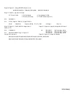
Page 6-7, Table 6-3, change DS 601 and F601 to read:
DS601
1450-0123
Indicator Light
08717
859-R-6
Sloan
F601
2110-0063
Fuse, 0.75A, 2A 250V
75915
312.750
Littlefuse
1400-0085
Holder -Fuse
75915
342004
Littlefuse
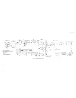
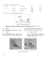
Page 7-9, Figure 7-3, make the following change to the schematic:
FIGURE 8-3. IEC POWER CONNECTION
Shielded 4-conductor cable and 3 additional color coded wires (white/blue, black and yellow) are replaced by a
shielded 7-conductor cable assembly. Pre-IEC receptacle for ac power connector also used.
8-10.
CHANGE IV
8-11.
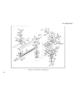
CARRIAGE ARM. Page 6-11, Figure 6-2, Legend,
delete, item 29, delete part no. for terminal
8-12.
CHANGE V
8-13.
PEN ASSEMBLY. Page 1-4, Table 1-2, should
include the following: Slidewire cleaner, slidewire lubricant, 2
pens, 1 btl green ink, 1 btl red ink, ink filling, syringe, rear
mating connector, appropriate graph paper, power cord (7.5 ft),
rack mounting brackets, dust cover, instruction manual.
Page 3-4, paragraph 3-34, 3-35, and Figure 3-3, replace with:
3-34.
INSTALL AN INK PEN
3-35.
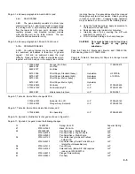
Use a hypodermic syringe; fill reservoir just
short of full. Force ink into the pen tip by fully
inserting the syringe into the filler opening and
squeeze gently. See Figure 8-4.
FIGURE 8-4. FILLING INK PEN
8-4
Summary of Contents for HP-7035B
Page 1: ...TECHNICAL MANUAL HEWLETT PACKARD MODEL HP 7035B ...
Page 9: ...FIGURE 1 4 DIMENSION DRAWING FIGURE 1 5 ACCESSORIES 1 3 ...
Page 12: ...FIGURE 1 7 TYPICAL FREQUENCY RESPONSE INPUT FILTER FIGURE 1 8 TYPICAL DYNAMIC RESPONSE 1 6 ...
Page 14: ...FIGURE 2 1 WING BRACKET INSTALLATION FIGURE 2 2 STACKED CONFIGURATION 2 2 ...
Page 16: ...FIGURE 3 1 FRONT PANEL CONTROLS 7035B AND 7035B 001 MODELS 3 2 ...
Page 20: ...FIGURE 4 1 BLOCK DIAGRAM FIGURE 4 2 DETAILED BLOCK DIAGRAM 4 2 ...
Page 48: ...TM 11 6625 2850 14 P FIGURE 6 1 EXPLODED VIEW CABINET 6 9 ...
Page 49: ...TM 11 6625 2850 14 P FIGURE 6 2 EXPLODED VIEW CARRIAGE ARM SHEET 1 OF 2 6 10 ...
Page 58: ...FIGURE 7 1 COMPONENT IDENTIFICATION FRAME 7 8 ...
Page 59: ...TM 11 6625 2850 14 P Figure 7 2 Component Identification Circuit Board 7 9 ...
Page 60: ...TM 11 6625 2850 14 P Figure 7 3 Schematic Model 7035B D 07035 92550 7 10 ...
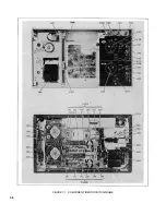
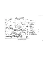
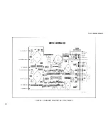
Page 62: ...TM 11 6625 2850 14 P FIGURE 8 1 COMPONENT IDENTIFICATION CIRCUIT BOARD 8 2 ...
Page 66: ...TM 11 6625 2850 14 P FIGURE 8 5 EXPLODED VIEW CARRIAGE ARM 8 6 ...

