background image

SECTION III

OPERATING INSTRUCTIONS

3-1.

OPERATING REQUIREMENTS

3-2.

GENERAL

3-3.

The basic function of the Model 7035B Recorder is to

produce graphic tracings showing the relationship between two
variable functions.  Slowly varying dc signals representing
these functions are applied to the input terminals of the
respective axes of the instrument, and its controls adjusted so
that the resulting graph will cover the desired scope of
operation.

CAUTION

Before attempting to operate this
instrument the user should study the
following paragraphs.

3-4.

CONTROLS, CONNECTORS, AND INDICATORS

3-5.

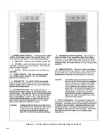
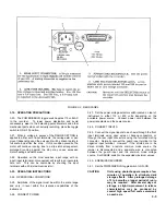
The front and rear panel controls, connectors, and

indicators are depicted and explained in
Figures 3-1 and 3-2.

3-6.

ELECTRICAL REQUIREMENTS

3-7.

OPERATING POWER

3-8.   The line power supplied to the recorder should be either
115 or 230 volts 10%, 50 to 60 Hz, single phase.  A voltage
conversion switch, see Figure 3-2, must be set to correspond
to the available supply voltage.  For 115 Vac use a 3/4 amp
fuse. For 230 Vac use a 3/8 amp fuse.

3-9.   INPUT SIGNALS

3-10. The recorder input terminals (+ and -) must be supplied
with a dc signal on each axis.  This signal should be in direct
proportion to the actual function unless a special relationship is
required, such as the logarithmic value of the input voltage.
These signals must vary at a rate within the response
capabilities of the instrument and have amplitudes within its
scale ranges.  If an excessive amount of ac noise is present in
the input signals, the response of the recorder may become
sluggish and erratic or oscillatory.

CAUTION   

Do not directly apply signals in excess of
250 volts on the X-axis or 175 volts on the
Y-axis.

3-11. GROUNDING

3-12. For optimum performance, the third prong of the ac
power cord must be grounded.  When operating from
ungrounded power sources, adequate grounding is mandatory.

3-13. RECORDING INPUT CONNECTIONS

3-14. Input terminals for each axis are located on the front
panel adjacent to the corresponding range switches.  Front
panel terminals will accept either "banana" plugs or open
wires.

3-15. CONNECTION TECHNIQUES FOR THE GUARD

SHIELD

3-16. Connect the recorder's guard shield in one of the
following ways:

a.

To the SOURCE ground when:

1.

Operating on low level ranges

2.

When ac noise pickup is a problem.

b.

To the negative input using the convenient shorting

straps when conditions 1 and 2 do not exist.

CAUTION

Do not leave the guard shield
disconnected or floating.  Tighten guard
strap securely.

3-17. MAXIMUM ALLOWABLE SOURCE IMPEDANCE

3-18. No restrictions except on fixed 1mv/in. (0.4 mv/cm)
range.  Up to 20k ohm source impedance will not appreciably
alter the recorder's performance.  Higher source impedance
will cause an increase in dead zone and a decrease in pen
speed.  Values up to approximately 100k may be compensated
for by adjusting the servo amplifier gain adjustment (front
panel).

3-1

Summary of Contents for HP-7035B

Page 1: ...TECHNICAL MANUAL HEWLETT PACKARD MODEL HP 7035B ...

Page 2: ...ating Instructions 3 3 3 24 Operational Conditions 3 3 3 26 Connect Power 3 3 3 28 Connect Inputs 3 3 3 30 Energize Recorder 3 3 Section Page 3 32 Install Paper 3 4 3 34 Install Pen 3 4 3 36 Zero Set 3 4 3 38 Lower Pen 3 4 IV THEORY OF OPERATION 4 1 General Operation Description 4 1 4 7 Circuit Description 4 1 V MAINTENANCE PERFORMANCE CHECKS AND ADJUSTMENTS 5 1 Introduction 5 1 5 3 Preventive Mai...

Page 3: ...tment 5 14 5 94 Calibration Adjustment 5 14 5 96 Phase Shift Adjustment 5 15 VI PARTS LIST 6 1 Introduction 6 1 6 3 Parts List 6 1 Section Page 6 4 Alphanumerical Table 6 1 6 6 Miscellaneous Parts 6 1 6 8 Recommended Spares 6 1 6 10 Code List of Manufacturers 6 1 6 12 Illustrated Parts Breakdown 6 1 VII TROUBLESHOOTING 7 1 Introduction 7 1 7 2 Content 7 1 7 4 Troubleshooting 7 1 7 5 Requirements 7...

Page 4: ...ection 5 4 5 9 Servo Motor Maintenance and Backlash Adjustments 5 5 5 10 Nylon Cable Attachment to Pen Block 5 6 5 11 Restringing Diagram 5 7 5 12 Y Axis Slewing Speed Test Setup 5 8 5 13 Slewing Speed Determination 5 9 5 14 X Axis Slewing Speed Test Setup 5 9 5 15 Y Axis Drive String Tension Check 5 10 5 16 Y Axis Backlash Adjustment Gear Adjusting Screw 5 10 5 17 Y Axis Backlash Adjustment Gear ...

Page 5: ...610 19C DLAR 4500 15 O 4 Reporting Equipment Improvement Recommendations EIR If your Recorder RO 458 V 1 U needs improvement let us know Send us an EIR You the user are the only one who can tell us what you don t like about your equipment Let us know why you don t like the design Tell us why a procedure is hard to perform Put it on an SF 368 Quality Deficiency Report Mail it to Commander US Army C...

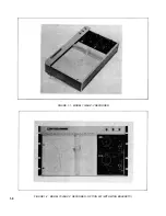
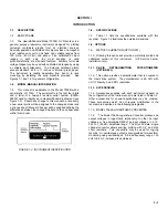
Page 6: ...FIGURE 1 1 MODEL 7035B X Y RECORDER FIGURE 1 2 MODEL 7035B X Y RECORDER OPTION 001 WITH WING BRACKETS 1 0 ...

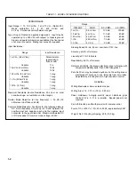
Page 7: ...fferences between the changed model and the one described within this manual FIGURE 1 3 INSTRUMENT IDENTIFICATION 1 6 SPECIFICATIONS 1 7 Table 1 1 lists the specifications available with this recorder Figure 1 4 illustrates the outside dimensions 1 8 OPTIONS 1 9 METRIC CALIBRATION OPTION 001 1 10 Ordering this option will provide a metrically scaled and calibrated version of this instrument HP Ser...

Page 8: ...ohm between the positive input and negative input and the negative input connected to the guard terminal Maximum allowable DC or DC plus peak AC common mode voltage is 500V Range Standard Metric DC CMR AC CMR 1 mV in 0 4 mV cm 130 dB 100 dB 10 mV in 4 mV cm 110 dB 80 dB 100 mV in 40 mV cm 90 dB 60 dB 1V in 400 mV cm 70 dB 40 dB 10 V in 4 V cm 50 dB 20 dB Slewing Speed 20 in s 50 cm nominal at 115V...

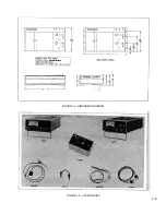
Page 9: ...FIGURE 1 4 DIMENSION DRAWING FIGURE 1 5 ACCESSORIES 1 3 ...

Page 10: ...nection to the 7035B Maximum input voltage is 600 volts peak The cable is terminated in a shielded dual banana plug 1 23 MODEL 10111A ADAPTER 1 24 The 10111A shielded banana post to female BNC converts banana post inputs on 7035B to shielded BNC inputs for low level signal work This adapter may be used in pairs for balanced input characteristics 1 25 MODEL 10002A B C D VOLTAGE DIVIDER PROBE 1 26 T...

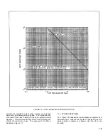
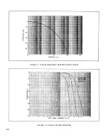
Page 11: ...he servo system s carrier frequency A built in low pass filter in both axes minimizes the effects of normal mode noise The response of this filter is illustrated in Figure 1 7 1 34 DYNAMIC RESPONSE 1 35 Figure 1 8 indicates the typical frequency response for a sinusoidal input Although the recorder is designed to record slowly varying dc voltages ac voltages up to a few Hz can be recorded 1 5 ...

Page 12: ...FIGURE 1 7 TYPICAL FREQUENCY RESPONSE INPUT FILTER FIGURE 1 8 TYPICAL DYNAMIC RESPONSE 1 6 ...

Page 13: ...ecautions should be taken when repackaging the recorder a Remove disposable inkpen Tape a piece of heavy recording paper to Autogrip table surface b Secure upper end of carriage arm and pen carriage to side of recorder to prevent movement while in transit with shipping clamp and pad assembly Part No 5080 7834 c If recorder is being returned for repair do not send power cord or accessory kit d Wrap...

Page 14: ...FIGURE 2 1 WING BRACKET INSTALLATION FIGURE 2 2 STACKED CONFIGURATION 2 2 ...

Page 15: ...he response capabilities of the instrument and have amplitudes within its scale ranges If an excessive amount of ac noise is present in the input signals the response of the recorder may become sluggish and erratic or oscillatory CAUTION Do not directly apply signals in excess of 250 volts on the X axis or 175 volts on the Y axis 3 11 GROUNDING 3 12 For optimum performance the third prong of the a...

Page 16: ...FIGURE 3 1 FRONT PANEL CONTROLS 7035B AND 7035B 001 MODELS 3 2 ...

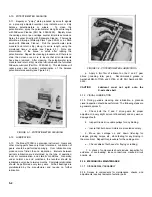
Page 17: ...in level within the response capabilities of the instrument 3 26 CONNECT POWER 3 27 Set the power voltage selector switch located on rear of instrument to either 115 or 230 volts depending on the available power source Connect power cord between the power receptacle and the power source 3 28 CONNECT INPUTS 3 29 Connect the signal inputs to each axis through the front input terminals using open wir...

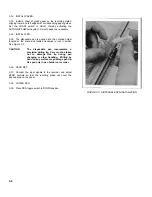
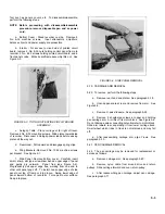
Page 18: ...d twisted clockwise to lock in holder See Figure 3 3 CAUTION The disposable pen incorporates a precision writing tip Care must be taken not to damage this tip during pen changing or other handling Writing by hand on any surface may damage pen tip Use pen only in pen holder on recorder 3 36 ZERO SET 3 37 Connect the input signals to the recorder and adjust ZERO controls so that the resulting graph ...

Page 19: ...e mechanically coupled the balance voltage changes value until the input signal is cancelled If the input data is constantly varying at rates within the capabilities of the instrument this rebalancing action is continuous and the rebalance potentiometers and the pens are always in a position directly proportional to the amplitude of the signals at the respective input terminals 4 6 AUTOGRIP HOLDDO...

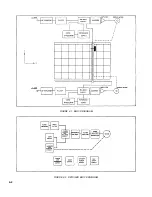
Page 20: ...FIGURE 4 1 BLOCK DIAGRAM FIGURE 4 2 DETAILED BLOCK DIAGRAM 4 2 ...

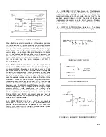
Page 21: ... component tolerances R 114 is a variable resistor that is factory adjusted to equalize the phase shift between axes A slight phase shift however will be noted when changing from range to range and when using the range selector vernier This phase shift may become very pronounced on the 1 mv inch 0 4 mv cm range if the input source impedance is extremely large or extremely small Diodes CR 101 and C...

Page 22: ...nd thermal emfs FIGURE 4 7 PHOTOCHOPPER AND BALANCE CIRCUIT 4 16 DIFFERENTIAL AMPLIFIER See Figure 4 8 The ac error signal from the Modulator and Balance Network is applied to the Gates of Q 101 and Q 102 through coupling capacitors C 109 and C 110 At time T1 a positive voltage is applied to the Gate of Q 101 the Source will follow the Gate and a positive voltage appears at the Source of Q 102 Thi...

Page 23: ...he line as determined by the error voltage applied to the photochopper FIGURE 4 11 MOTOR CONTROL AND DEMODULATOR Mode 1 Current flows from T 601 through B 101 A CR 108 CR 110 Q 110 R 115 and B through CR 107 back to T 601 The motor will rotate right Mode 2 Current flowing from T 601 is blocked by A Q 110 No current will flow and motor B will not rotate Mode 3 Current flows from T 601 through CR 10...

Page 24: ...ions of the required firing voltage FIGURE 4 13 NEON DRIVER 4 23 AUTOGRIP POWER SUPPLY See Figure 4 14 The Autogrip power supply is also located on the amplifier printed circuit board The power is obtained from the high voltage secondary winding on the main power transformer T 601 and the remainder of the supply is composed of resistors R501 through R505 diodes CR501 through 504 and dual capacitor...

Page 25: ... operation local air contamination and climatic conditions Generally under normal use and conditions cleaning intervals should be nine to twelve months Cleaning routine should include the following a Remove platen and bottom cover See paragraph 5 18 b In accessible areas and where there is only dust accumulation cleaning can be accomplished with an air gun In more accessible areas and where the ai...

Page 26: ...than no lubrication Intervals between periodic lubrication are determined by the type of operation local air contamination and climatic conditions Generally under normal use and conditions the recorder should be lubricated every nine to twelve months Complete relubrication should be performed every two years All ball bearings are prelubricated by the manufacturer and require no further lubrication...

Page 27: ...e of panel and gently pry outward Panel free see Figure 5 4 Progressively pull upper edge free working from one end to other until panel pops off To install hook upper edge of side panel over top of frame or into groove Swing lower edge of panel toward bottom of recorder Force past outer surface Snap into place FIGURE 5 4 SIDE PANEL REMOVAL 5 19 CARRIAGE ARM REMOVAL 5 20 To remove perform the foll...

Page 28: ...d to slidewire d More slidewire assembly upwards being careful not to damage wiper See Figure 5 8 FIGURE 5 7 REMOVAL OF X AXIS REBALANCE POTENTIOMETER FIGURE 5 8 X AXIS WIPER PROTECTION e Install new slidewire assembly Part No 07035 80730 5 25 WIPER REPLACEMENT X AXIS 5 26 The wiper is made of a soft metal to absorb wear It is located on the pen motor block at the upper end of the carriage arm New...

Page 29: ...emove pen carriage arm See paragraph 5 22 e Remove wiper assembly from pen block by unscrewing 1 0 80 screw and nut f Install new wiper Part No 5080 7706 g After reassembling pen carriage adjust pen carriage See paragraph 5 71 5 31 SERVO MOTOR MAINTENANCE 5 32 The magnetic field strength of the servo motor will weaken if the rotor is removed from within the magnet Upon reassembly it will be imposs...

Page 30: ... into top of spring slot so they are below surface of end bell Solder motor wires to the correct lugs j Operate recorder If pen drives into stops instead of seeking null motor polarity has been inadvertently reversed Reconnect motor wires to opposite terminal lugs k Run recorder through complete performance check If brushes are not seating well apply a 0 3 Hz sine wave to recorder adjust to 85 of ...

Page 31: ...kwise direction pass it in front and around left hand edge of cable yoke Point G and pass it to screw Point H on Y motor block g Pass cable around screw Point H in clockwise direction Firmly pull on cable to keep the cable taut and tighten screw NOTE There is a nut on the bottom of Nut H Make sure this is tight h Check cable tension as described in paragraph 5 75 i Clip off the excess wire 5 45 EL...

Page 32: ...34 mm e If pen does not stop within tolerance adjust calibration control R 126 f Reduce voltage applied in steps of 0 1V at each step g After each step pen should stop at 1 in 2 cm intervals within 0 014 in 0 34 mm 5 56 X AXIS ACCURACY AND LINEARITY a Connect DC Standard to X input terminals b Place pen at exactly zero on X axis and at 3 5 in 9 cm on Y axis c Apply 1 volt to X input terminals d Pe...

Page 33: ...on on paper c Set Function Generator to 10 V peak to peak sine wave and sweep frequency 3 Hz around line frequency d Pen deflection shall not exceed 0 2 in 5 mm with pen at any position on paper e Repeat at all fixed attenuator positions for Y inputs f Repeat test for X axis Pen deflection is same 5 62 MECHANICAL ADJUSTMENTS 5 63 PROCEDURE 5 64 Any adjustment to the instrument is deemed necessary ...

Page 34: ...e to extreme left hand position and stand recorder on its right side i Remove bottom cover j Slightly loosen two motor clamping screws from bottom of the recorder Rotate motor slightly first in one direction and then in the other while moving pen gear back and forth until motor pinion rotates freely with minimum backlash This procedure varies mesh between motor pinion and pen drive gear due to an ...

Page 35: ... the vertical wall of the motor assembly trough shall be between the limits of 15 ounces and 32 ounces See Figure 5 20 Some adjustment is possible by loosening and repositioning idler pulleys 5 76 If adjustment is not possible by moving pulleys a new cable must be installed making sure that at time of installation the tension is correct See paragraph 5 44 5 77 X AXIS DRIVE BELT TENSION CHECK ADJUS...

Page 36: ...FIGURE 5 19 Y AXIS ALIGNMENT FIGURE 5 20 X AXIS CABLE TENSION CHECK FIGURE 5 21 X AXIS DRIVE BELT TENSION CHECK 5 12 ...

Page 37: ...is drive bearings the X axis drive cable must be partially or completely removed depending on which bearing is affected See Figure 5 23 5 88 PULLEY BEARING REPLACEMENT To replace either pulley bearing proceed as follows a Remove rear hood and platen See paragraph 5 18 b Move pen carriage to its extreme position away from affected pulley c Apply masking tape to remaining pulley and drive sheave so ...

Page 38: ... frequency Function Generator to X and Y input terminals Set up for triangular output wave of 500 mV pk pk at 0 1 Hz b Set X RANGE switch to 100 mV in 40 mV cm Y RANGE switch to 1V in 0 4V cm c Turn on recorder d Adjust R237 until minimum retrace error exists e Pen speed should not exceed 1 in sec 0 4 cm sec f Similarly set Y RANGE switch to 100 mV in 40 mV cm X RANGE switch to 1V in 0 4V cm g Adj...

Page 39: ... of the retrace curves described in paragraph 5 91 the attenuator switches may be set to identical values in both X and Y to produce a straight line of 45 degree angle If the retrace test made on X and Y demonstrates zero trace the gap which appears in the 45 degree retrace line will be due to a phase difference or time lag between the two recording axes Phase adjust is accomplished by adjusting R...

Page 40: ...will be listed by part number description and manufacturer 6 8 RECOMMENDED SPARES 6 9 Table 6 3 lists all components with mortality experience Recommended quantities to stock for maintaining the instrument for a one year period are specified in the quantity column 6 10 CODE LIST OF MANUFACTURERS 6 11 Table 6 4 lists the five digit code number assigned to a specific manufacturer This table is a cro...

Page 41: ... USED C208 0180 0291 C FXD ELECT 1 0 UF 10 35VDCW 56289 150D105X9035A2 DYS C209 0160 0161 C FXD MY 0 01 UF 10 200VDCW 56289 192P10392 PTS C210 0160 0161 C FXD MY 0 01 UF 10 200VDCW 56289 192P10392 PTS C211 NOT USED C212 0180 0374 C FXD TANT 10 UF 10 20VDCW 56289 150D106X9020B2 DYS C213 0180 0374 C FXD TANT 10 UF 10 20VDCW 56289 150D106X9020B2 DYS C214 0180 0137 C FXD ELECT 100 UF 20 10VDCW 56289 1...

Page 42: ... 895 W C2A 22K F601 2110 0065 1 FUSE 0 375A 250V FOR 230V LINE 75915 312 375 F601 2110 0063 1 FUSE 0 75A 250V FOR 115V LINE 75915 312 750 F601 1400 0084 1 FUSEHOLDER EXTRACTOR POST TYPE 75915 342014 J101 1510 0008 4 BINDING POST RED 28480 1510 0008 J102 1510 0008 BINDING POST RED 28480 1510 0008 J103 1910 0009 1 J201 1510 0008 BINDING POST RED 28480 1510 0008 J202 1510 0008 BINDING POST RED 28480 ...

Page 43: ...1 4W 01121 CB 3331 R143 0683 3945 2 R FXD COMP 390K OHM 5 1 4W 01121 CB 3945 R144 0684 4731 R FXD COMP 47K OHM 10 1 4W 01121 CB 4731 R145 0683 2225 2 R FXD COMP 2 2K OHM 5 1 4W 01121 CB 2225 R147 0684 1841 2 R FXD COMP 180K OHM 10 1 4W 01121 CB 1841 R148 0684 1041 R FXD COMP 100K OHM 10 1 4W 01121 CB 1041 R149 0684 1021 R FXD COMP 1000 OHM 10 1 4W 01121 CB 1021 R150 0684 3331 R FXD COMP 33K OHM 10...

Page 44: ... 0684 1021 R FXD COMP 1000 OHM 10 1 4W 01121 CB 1021 R250 0684 3331 R FXD COMP 33K OHM 10 1 4W 01121 CB 3331 R251 0684 1021 R FXD COMP 1000 OHM10 1 4W 01121 CB 1021 R252 0684 4711 R FXD COMP 470 OHM 10 1 4W 01121 CB 4711 R253 0684 1521 R FXD COMP 1500 OHM 10 1 4W 01121 CB 1521 R254 0683 4725 R FXD COMP 4700 OHM 5 1 4W 01121 CB 4725 R255 0813 0046 R FXD WW 1 OHM 10 3W 28480 0813 0046 R256 0683 6215...

Page 45: ...35 01030 07035 01000 Panel Side RH and LH H P 07035 01000 07004 01860 Panel front rear H P 07004 01860 07035 61440 Cable Assembly 07035 00511 Cover Bottom H P 07035 00511 07035 61660 Rear Hood Assy Standard H P 07035 61660 07035 61670 Rear Hood Assy Metric H P 07035 61670 07035 64270 Hood Assembly Metric Option 001 07004 60640 Solenoid Pen lit Serial Prefix 826 and below H P require index pointer ...

Page 46: ... DS 302 2140 0047 Lamp Neon 1 10w 0 8ma G E A1C 2 DS 303 DS 304 68K ohms DS 304 DS 601 1450 0495 Indicator Light Sloan Co 859 W ZA 22K F 601 2110 0063 Fuse 750 mA Littlefuse 312 750 5 2110 0065 Fuse 375 mA Littlefuse 312 375 K 401 07004 Solenoid Pen Lift H P 07004 60650 1 60650 09125 Plunger Assembly Solenoid H P 09125 20350 1 20350 Q 101 Q 102 1855 0067 Transistor Field Effect Siliconix Inc E 101...

Page 47: ...H P 07035 62160 1 62160 5060 6428 Pen Holder H P 5060 6428 1 TABLE 6 4 MANUFACTURER S CODE LIST MFR NO MANUFACTURER S NAME ADDRESS ZIP CODE 01121 Alien Bradley Company Milwaukee Wis 53204 04713 Motorola Semiconductor Products Inc Phoenix Ariz 85008 07263 Fairchild Camera Inst Corp Semiconductor Div Mountain View Calif 94040 08806 G E Co Miniature Lamp Dept Cleveland Ohio 44112 14655 Cornell Dubili...

Page 48: ...TM 11 6625 2850 14 P FIGURE 6 1 EXPLODED VIEW CABINET 6 9 ...

Page 49: ...TM 11 6625 2850 14 P FIGURE 6 2 EXPLODED VIEW CARRIAGE ARM SHEET 1 OF 2 6 10 ...

Page 50: ... 20200 Pulley Return Lower Hewlett Packard 37 07035 62420 Cleat Motor Assembly Hewlett Packard 38 07035 20240 Stud Pulley Return Hewlett Packard 39 07035 20280 Wheel Pen Arm Hewlett Packard 40 07035 20330 Mounting Block Pen Arm Hewlett Packard 41 07035 20350 Screw Shoulder Hewlett Packard 42 07005 00730 Pointer Index X Axis Hewlett Packard 43 07035 22020 Flywheel Hewlett Packard 44 07035 20310 Pul...

Page 51: ...t of bracketing should be established such as determining which circuits or sections are not operating or are operating abnormally This is generally the fastest method to locate trouble in a closed loop circuit When troubleshooting utilize the photographs and schematics presented in this section Figures 7 1 through 7 3 7 7 TROUBLESHOOTING INDEX 7 8 The troubleshooting index Table 7 1 lists other p...

Page 52: ... cm range only and or increase amplifier gain paragraph 5 92 c Drive string too loose Measure c Tighten drive string paragraph 5 67 tension per paragraph 5 66 d Pen carriage wheels set too tight d Adjust pen carriage per paragraph 5 71 e Insufficient backlash in gears too e Adjust backlash paragraph 5 69 tight f Motor brushes excessively worn f Replace brushes paragraph 5 38 g Pen speed too fast R...

Page 53: ...nominal source impedance Extremes filter can be compensated for only by reducing the pen speed thereby reducing the phase shift b Operating on ranges other than b Possible cures calibrated positions 1 Adjust R 114 2 Reduce pen speed c Phase relationship problem in c Examine signal source signal source d Phase adjustment R 114 mis d Adjust R 114 per paragraph 5 97 adjusted e Pen carriage wheels too...

Page 54: ...ing too loose Measure a Tighten drive string see seems to occasionally per paragraph 5 66 paragraph 5 67 bind or stick b Pen carriage wheels set too tight b Adjust pen carriage per paragraph 5 71 c Insufficient backlash in gears too c Adjust backlash paragraph 5 69 tight d Motor brushes excessively worn d Replace brushes see paragraph 5 38 e Motor brush stuck held off e Free up brush see paragraph...

Page 55: ... mv cm and or increase amplifier range only gain see paragraph 5 92 c Bearing in drive train faulty c Replace bearing see paragraph 5 87 d Faulty neon bulb in photochopper d Replace bulb aging not required e Excessive differential noise on e See Table 1 1 input signal f Excessive friction f Clean and lubricate per paragraphs 5 9 and 5 12 17 Maximum pen speed too a Power line voltage too low Pen a ...

Page 56: ...0 22 One axis runs erratically a Motor brush not properly seated a Inspect brush Replace at high speed in one or both to commutator per paragraph 5 38 or directions run in motor to seat brush b Motor brush tends to cock in b Replace motor per one direction of rotation and paragraphs 5 34 and 5 35 binds in brush holder 23 Slewing one axis causes a CR 111 open a Replace disturbance on other axiis b ...

Page 57: ...ears and motor mechanically free and b Motor brush stuck held off b Free up brush see electronics providing commutator paragraph 5 39 proper drive signal to motor 30 Recorder dives hard to a Faulty slidewire wiper a Replace wiper see end of scale will not paragraphs 5 26 and 5 30 balance b Open In balance circuit b Check balance circuits in fig 7 3 to locate faulty components c Phase reversal in s...

Page 58: ...FIGURE 7 1 COMPONENT IDENTIFICATION FRAME 7 8 ...

Page 59: ...TM 11 6625 2850 14 P Figure 7 2 Component Identification Circuit Board 7 9 ...

Page 60: ...TM 11 6625 2850 14 P Figure 7 3 Schematic Model 7035B D 07035 92550 7 10 ...

Page 61: ... 2 1 change Rack Mount Brackets part no to 07035 00490 Page 6 3 Table 6 1 change J 601 part no to 8120 3148 Page 6 6 Table 6 2 Spare Parts change the following items Power Cord 8120 1348 Panel Side RH LH 07035 00071 Panel Front and Rear 07035 00061 Rear Hood Assy Stnd 07035 62570 Rear Hood Assy Metric 07035 62571 Page 6 11 Figure 6 2 items 47 and 48 part no s are 47 Block Pen Arm 07034 60320 48 Pe...

Page 62: ...TM 11 6625 2850 14 P FIGURE 8 1 COMPONENT IDENTIFICATION CIRCUIT BOARD 8 2 ...

Page 63: ...08717 859 R 6 Sloan F601 2110 0063 Fuse 0 75A 2A 250v 75915 312 750 Littlefuse 1400 0085 Holder Fuse 75915 342004 Littlefuse Page 6 3 Table 6 1 change J601 and P601 to read J601 8120 0078 Power Cord 0903 KH 4147 Belden P601 12 51 0148 Connector AC Power 87930 1065 1 Tower Mfg Page 6 5 Table 6 1 change S601 to read S601 3101 0033 Switch Slide Power Conversion 79727 6510C Continental Page 6 6 Table ...

Page 64: ... used 8 10 CHANGE IV 8 11 CARRIAGE ARM Page 6 11 Figure 6 2 Legend delete item 29 delete part no for terminal 8 12 CHANGE V 8 13 PEN ASSEMBLY Page 1 4 Table 1 2 should include the following Slidewire cleaner slidewire lubricant 2 pens 1 btl green ink 1 btl red ink ink filling syringe rear mating connector appropriate graph paper power cord 7 5 ft rack mounting brackets dust cover instruction manua...

Page 65: ...e Page 6 6 Table 6 2 Mechanical Electric add 17999 15126 Pen Cleaning Wire H P 17999 15126 Page 6 6 Table 6 2 Accessory Kit Paper Ink change to read as follows 17999 09423 Syringe Pen filler H P 17999 09473 9260 0128 Ink Red 9260 0127 Ink Blue 9270 1006 Chart Paper Standard heavy Gubelman H 10070 A 9270 1007 Chart Paper Standard light Gubelman L 10070 A 9270 1023 Chart Paper Metric heavy Gubelman ...

Page 66: ...TM 11 6625 2850 14 P FIGURE 8 5 EXPLODED VIEW CARRIAGE ARM 8 6 ...

Page 67: ...8 3250 Resistor Mtl Flm 1 71k 1 1 8W Int l Resist CEA T 2 Page 7 9 Figure 7 3 X AXIS BLOCK change value of Page 6 11 Figure 6 2 Legend change item 48 to read R225 to 1 71k 8 16 CHANGE VII 48 0035 60180 Pen Scale Assy Blank 07035 60181 Pen Scale Assy English 8 17 COLOR SCHEME Page 1 3 Figure 1 4 07035 60182 Pen Scale Assy Metric change trim to aluminum Page 6 9 Figure 6 1 change the following PEN S...

Reviews: