SECTION II
INSPECTION AND INSTALLATION
2-1.
INTRODUCTION
2-2.
This section provides information for incoming
inspection, installation, storage, and shipping.
2-3.
INCOMING INSPECTION
2-4.
MECHANICAL CHECKS
2-5.
Inspect the instrument for mechanical damage,
scratches, dents, or other defects. Also check the cushioning
materials for signs of severe stress.
2-6.
ELECTRICAL CHECKS
2-7.
The electrical performance of the instrument should be
verified upon receipt. Performance checks, suitable for
incoming inspection, are presented in Section V.
2-8.
DAMAGE CLAIMS
2-9.
If the instrument is damaged in transit, or fails to meet
specifications upon receipt, follow procedures as outlined in
paragraph O-3.
2-10. STORAGE
2-11. If the instrument is to be stored for a period of time, the
disposable pen should be removed and the upper part of the
carriage arm and pen carriage tied to the side of the instrument
to prevent damage during handling. Seal the instrument in a
moisture-proof covering and repackage in a container similar to
the original factory carton.
2-12. SHIPPING
2-13. The following precautions should be taken when
repackaging the recorder:
a.
Remove disposable inkpen. Tape a piece of heavy
recording paper to Autogrip table surface.
b.
Secure upper end of carriage arm and pen carriage to
side of recorder to prevent movement while in transit with
shipping clamp and pad assembly (Part No. 5080-7834).
c.
If recorder is being returned for repair, do not send
power cord or accessory kit.
d.
Wrap instrument in heavy paper or plastic and
surround with three to four inches of shock-absorbing material
to cushion and prevent movement inside shipping container.
The container should be sufficiently durable to prevent damage
to instrument during handling.
2-14. RECORDER INSTALLATION
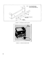
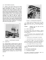
2-15. This recorder requires no physical installation for table
top operation. The accessory wing brackets provided allow
installation on standard 19-inch rack console if desired. To
install, refer to Figure 2-1.
2-16. COOLING
2-17. Cooling is provided by convection. The location or
mounting of the instrument must ensure adequate air
circulation.
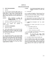
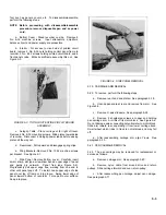
2-18. STACKING H-P INSTRUMENTS
2-19. The 7035B is equipped with special feet which allow it to
be stacked on other H-P instruments. Figure 2-2 shows the
7035B stacked on a 7560A and a 3300A. The rear tilt stand
provides easy viewing of the chart.
2-1
Summary of Contents for HP-7035B
Page 1: ...TECHNICAL MANUAL HEWLETT PACKARD MODEL HP 7035B ...
Page 9: ...FIGURE 1 4 DIMENSION DRAWING FIGURE 1 5 ACCESSORIES 1 3 ...
Page 12: ...FIGURE 1 7 TYPICAL FREQUENCY RESPONSE INPUT FILTER FIGURE 1 8 TYPICAL DYNAMIC RESPONSE 1 6 ...
Page 14: ...FIGURE 2 1 WING BRACKET INSTALLATION FIGURE 2 2 STACKED CONFIGURATION 2 2 ...
Page 16: ...FIGURE 3 1 FRONT PANEL CONTROLS 7035B AND 7035B 001 MODELS 3 2 ...
Page 20: ...FIGURE 4 1 BLOCK DIAGRAM FIGURE 4 2 DETAILED BLOCK DIAGRAM 4 2 ...
Page 48: ...TM 11 6625 2850 14 P FIGURE 6 1 EXPLODED VIEW CABINET 6 9 ...
Page 49: ...TM 11 6625 2850 14 P FIGURE 6 2 EXPLODED VIEW CARRIAGE ARM SHEET 1 OF 2 6 10 ...
Page 58: ...FIGURE 7 1 COMPONENT IDENTIFICATION FRAME 7 8 ...
Page 59: ...TM 11 6625 2850 14 P Figure 7 2 Component Identification Circuit Board 7 9 ...
Page 60: ...TM 11 6625 2850 14 P Figure 7 3 Schematic Model 7035B D 07035 92550 7 10 ...
Page 62: ...TM 11 6625 2850 14 P FIGURE 8 1 COMPONENT IDENTIFICATION CIRCUIT BOARD 8 2 ...
Page 66: ...TM 11 6625 2850 14 P FIGURE 8 5 EXPLODED VIEW CARRIAGE ARM 8 6 ...

