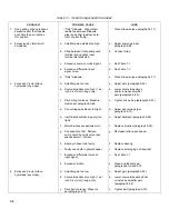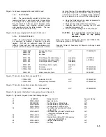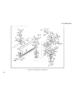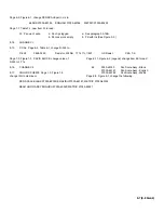
TABLE 7-1. 7035B TROUBLESHOOTING INDEX (Continued)
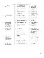
PROBLEM
POSSIBLE CAUSE
CURE
4.
(cont)
d.
X-axis slider rod bearings too
d.
Adjust slide rod bearings
tight.
(paragraph 5-85).
e.
Insufficient backlash in gears
e.
Adjust backlash (paragraph 5-83).
(too tight).
f.
Motor brushes excessively worn.
f.
Replace brushes (paragraph 5-38).
g.
Pen speed too fast. Retrace
g.
Decrease retrace pen
error should be small only at pen
speed.
speeds below 1 inch/sec.
h.
Bearing in drive train faulty.
h.
Replace bearing (paragraph 5-87).
i.
Faulty neon bulb in photochopper.
i.
Replace faulty bulb (aging not required).
j.
Excessive differential noise on
j.
See Table 1-1.
input signal.
k.
Grease on drive belt.
k.
Clean
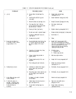
5.
Excessive hysteresis in
a.
Source impedance too high or low
a.
Adjust R-114 (paragraph 5-97).
45 retrace (X and Y steep
(1 my/inch range only) causing
This control will adjust the phasing
angle retrace O. K.).
excessive phase shift in input
nominal source impedance. Extremes
filter.
can be compensated for only by
reducing the pen speed, thereby
reducing the phase shift.
b.
Operating on ranges other than
b.
Possible cures:
calibrated positions.
1.
Adjust R-114.
2.
Reduce pen speed.
c.
Phase relationship problem in
c.
Examine signal source.
signal source.
d.
Phase adjustment (R-114) mis -
d.
Adjust R-114 per paragraph 5-97.
adjusted.
e.
Pen carriage wheels too loose.
e.
Adjust pen carriage wheels
(paragraph 5-71).
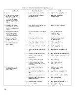
6.
Calibration incorrect.
a.
Calibration controls (front panel
a.
Calibrate unit per paragraph 5-95.
screw driver adj) incorrectly
adjusted.
b.
Recording paper inaccurate due to
b.
Calibrate unit per paragraph 5-95.
poor printing or environmental
effects.
7.
High voltage ranges won't
Leakage on surface of printed
Wash board per paragraph 5-9.
hold calibration.
circuit board.
8.
X-axis arm seems to
a.
Upper support screws (two) not
a.
Align arm and tighten (see
wobble - not rigidly held.
tight (see figure 5-6).
paragraph 5-73).
(Slight vertical wobble at
zero end of arm is
b.
X-axis slider rod bearings too
b.
Adjust slider rod bearing
normal.)
loose.
(paragraph 5-85).
7-3
Summary of Contents for HP-7035B
Page 1: ...TECHNICAL MANUAL HEWLETT PACKARD MODEL HP 7035B ...
Page 9: ...FIGURE 1 4 DIMENSION DRAWING FIGURE 1 5 ACCESSORIES 1 3 ...
Page 12: ...FIGURE 1 7 TYPICAL FREQUENCY RESPONSE INPUT FILTER FIGURE 1 8 TYPICAL DYNAMIC RESPONSE 1 6 ...
Page 14: ...FIGURE 2 1 WING BRACKET INSTALLATION FIGURE 2 2 STACKED CONFIGURATION 2 2 ...
Page 16: ...FIGURE 3 1 FRONT PANEL CONTROLS 7035B AND 7035B 001 MODELS 3 2 ...
Page 20: ...FIGURE 4 1 BLOCK DIAGRAM FIGURE 4 2 DETAILED BLOCK DIAGRAM 4 2 ...
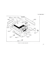
Page 48: ...TM 11 6625 2850 14 P FIGURE 6 1 EXPLODED VIEW CABINET 6 9 ...
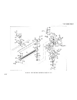
Page 49: ...TM 11 6625 2850 14 P FIGURE 6 2 EXPLODED VIEW CARRIAGE ARM SHEET 1 OF 2 6 10 ...
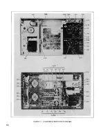
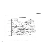
Page 58: ...FIGURE 7 1 COMPONENT IDENTIFICATION FRAME 7 8 ...
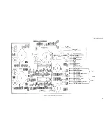
Page 59: ...TM 11 6625 2850 14 P Figure 7 2 Component Identification Circuit Board 7 9 ...
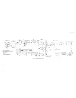
Page 60: ...TM 11 6625 2850 14 P Figure 7 3 Schematic Model 7035B D 07035 92550 7 10 ...
Page 62: ...TM 11 6625 2850 14 P FIGURE 8 1 COMPONENT IDENTIFICATION CIRCUIT BOARD 8 2 ...
Page 66: ...TM 11 6625 2850 14 P FIGURE 8 5 EXPLODED VIEW CARRIAGE ARM 8 6 ...


