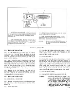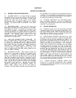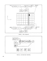
first, such as panels, covers, etc. To disassemble/assemble,
perform the following steps:
NOTE
Before proceeding with disassemble/assemble
procedure, remove disposable pen and ac power
cord.
a.
Bottom Cover - Stand recorder on side. Remove 8
No. 6-32 machine screws. Input attenuators, amplifiers,
balance circuit, and power supply are accessible.
b.
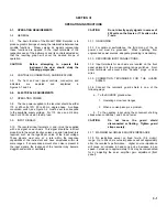
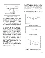
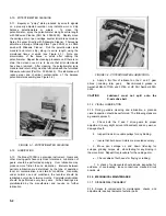
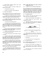
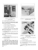
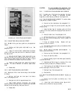
Interior - For access to circuit side of printed circuit
board, remove 3 No. 8-32 nuts holding control panel frame to
recorder, 3 No. 6-32 screws holding printed circuit board, and 6
front panel knobs. Entire board/frame assembly tilts out. See
Figure 5-3.
FIGURE 5-3. TILTING OUT ENTIRE CIRCUIT BOARD
ASSEMBLY
c.
Autogrip Table - Place carriage at far right of travel.
Remove 4 No. 8-32 mounting screws. Slide platen toward side
of recorder. Disconnect 2 Autogrip power leads before easing
platen all the way out.
d.
Rear Hood - Pull upward and disengage spring clips.
e.
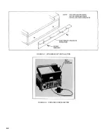
Wing Brackets -Remove 2 No. 10-32 machine screws
per bracket. See Figure 2-1.
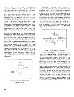
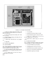
f.
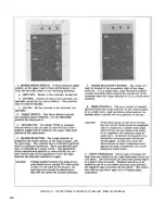
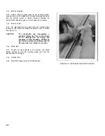
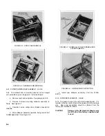
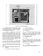
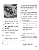
Side Panel -Remove bottom cover. Carefully insert
small, sharp, slot type screwdriver behind upper edge of panel
and gently pry outward. Panel free (see Figure 5-4).
Progressively pull upper edge free, working from one end to
other until panel pops off. To install, hook upper edge of side
panel over top of frame or into groove. Swing lower edge of
panel toward bottom of recorder. Force past outer surface.
Snap into place.
FIGURE 5-4. SIDE PANEL REMOVAL
5-19. CARRIAGE ARM REMOVAL
5-20. To remove, perform the following steps.
a.
Remove rear hood and platen. See paragraph 5-18.
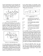
b.
Unsnap pen scale at rear and remove from arm. See
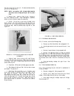
Figure 5-5.
c.
Remove X-axis slidewire. See paragraph 5-24.
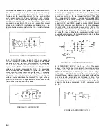
d.
Remove 2 shouldered screws at upper end holding
pen carriage arm. Arm lifts off its motor block. See Figure 5-6.
Do not damage wires connecting potentiometer to motor block.
Slide arm toward rear, separating it from lower carriage track.
Small wheel which rides in track is not retained and may fall
off.
e.
After reassembling carriage arm, align Y-axis. See
paragraph 5-73.
5-21. PEN CARRIAGE REMOVAL
5-22. The pen carriage may be removed for replacement or
service as follows:
a.
Remove carriage arm. See paragraph 5-20.
b.
Remove nylon cable from around drive and return
pulleys. Slide carriage forward and over return pulley.
c.
After reassembling pen carriage, adjust pen carriage.
See paragraph 5-71
.
5-3
Summary of Contents for HP-7035B
Page 1: ...TECHNICAL MANUAL HEWLETT PACKARD MODEL HP 7035B ...
Page 9: ...FIGURE 1 4 DIMENSION DRAWING FIGURE 1 5 ACCESSORIES 1 3 ...
Page 12: ...FIGURE 1 7 TYPICAL FREQUENCY RESPONSE INPUT FILTER FIGURE 1 8 TYPICAL DYNAMIC RESPONSE 1 6 ...
Page 14: ...FIGURE 2 1 WING BRACKET INSTALLATION FIGURE 2 2 STACKED CONFIGURATION 2 2 ...
Page 16: ...FIGURE 3 1 FRONT PANEL CONTROLS 7035B AND 7035B 001 MODELS 3 2 ...
Page 20: ...FIGURE 4 1 BLOCK DIAGRAM FIGURE 4 2 DETAILED BLOCK DIAGRAM 4 2 ...
Page 48: ...TM 11 6625 2850 14 P FIGURE 6 1 EXPLODED VIEW CABINET 6 9 ...
Page 49: ...TM 11 6625 2850 14 P FIGURE 6 2 EXPLODED VIEW CARRIAGE ARM SHEET 1 OF 2 6 10 ...
Page 58: ...FIGURE 7 1 COMPONENT IDENTIFICATION FRAME 7 8 ...
Page 59: ...TM 11 6625 2850 14 P Figure 7 2 Component Identification Circuit Board 7 9 ...
Page 60: ...TM 11 6625 2850 14 P Figure 7 3 Schematic Model 7035B D 07035 92550 7 10 ...
Page 62: ...TM 11 6625 2850 14 P FIGURE 8 1 COMPONENT IDENTIFICATION CIRCUIT BOARD 8 2 ...
Page 66: ...TM 11 6625 2850 14 P FIGURE 8 5 EXPLODED VIEW CARRIAGE ARM 8 6 ...

