3-32. INSTALL PAPER
3-33. Install a sheet of graph paper on the recording platen,
aligning lower and left edges with corresponding paper guides.
Set the CHART switch to HOLD, thereby activating the
AUTOGRIP holddown system. Smooth paper as necessary.
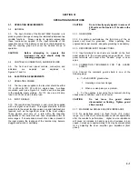
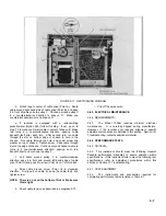
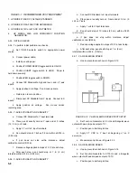
3-34. INSTALL PEN
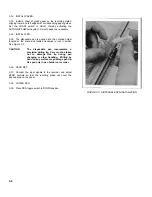
3-35. The disposable pen is pushed into the notched holder
located on the scale, and twisted clockwise to lock in holder.
See Figure 3-3.
CAUTION
The disposable pen incorporates a
precision writing tip. Care must be taken
not to damage this tip during pen
changing or other handling. Writing by
hand on any surface may damage pen tip.
Use pen only in pen holder on recorder.
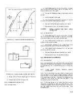
3-36. ZERO SET
3-37. Connect the input signals to the recorder and adjust
ZERO controls so that the resulting graph will cover the
desired area on the paper.
3-38. LOWER PEN
3-39. Place PEN toggle switch to DOWN position.
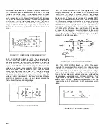
FIGURE 3-3. DISPOSABLE PEN INSTALLATION
3-4
Summary of Contents for HP-7035B
Page 1: ...TECHNICAL MANUAL HEWLETT PACKARD MODEL HP 7035B ...
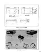
Page 9: ...FIGURE 1 4 DIMENSION DRAWING FIGURE 1 5 ACCESSORIES 1 3 ...
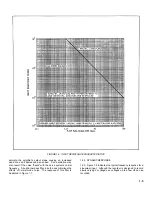
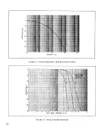
Page 12: ...FIGURE 1 7 TYPICAL FREQUENCY RESPONSE INPUT FILTER FIGURE 1 8 TYPICAL DYNAMIC RESPONSE 1 6 ...
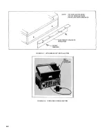
Page 14: ...FIGURE 2 1 WING BRACKET INSTALLATION FIGURE 2 2 STACKED CONFIGURATION 2 2 ...
Page 16: ...FIGURE 3 1 FRONT PANEL CONTROLS 7035B AND 7035B 001 MODELS 3 2 ...
Page 20: ...FIGURE 4 1 BLOCK DIAGRAM FIGURE 4 2 DETAILED BLOCK DIAGRAM 4 2 ...
Page 48: ...TM 11 6625 2850 14 P FIGURE 6 1 EXPLODED VIEW CABINET 6 9 ...
Page 49: ...TM 11 6625 2850 14 P FIGURE 6 2 EXPLODED VIEW CARRIAGE ARM SHEET 1 OF 2 6 10 ...
Page 58: ...FIGURE 7 1 COMPONENT IDENTIFICATION FRAME 7 8 ...
Page 59: ...TM 11 6625 2850 14 P Figure 7 2 Component Identification Circuit Board 7 9 ...
Page 60: ...TM 11 6625 2850 14 P Figure 7 3 Schematic Model 7035B D 07035 92550 7 10 ...
Page 62: ...TM 11 6625 2850 14 P FIGURE 8 1 COMPONENT IDENTIFICATION CIRCUIT BOARD 8 2 ...
Page 66: ...TM 11 6625 2850 14 P FIGURE 8 5 EXPLODED VIEW CARRIAGE ARM 8 6 ...

