SECTION VIII
BACKDATING
8-1.
REQUIREMENTS
8-2.
DEFINITIONS
8-3.
This section provides information on serial prefixes
below 845. Table 8-1 is a tabular presentation of the serial
prefix numbers and the corresponding change numbers. To
adapt this manual to the instrument on hand, determine the
serial prefix of the instrument, then refer to Table 8-1 and make
the appropriate changes to the manual.
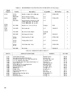
TABLE 8-1. SERIAL PREFIX/CHANGE
NUMBER REFERENCES
Serial Prefix
Change
1113A-1049A
I
1048A-1040A
I, II
1039A-1025A
I, II, III
1024A-1017A
I, II, III, IV
1016A-926
I thru V
925-845
I thru VI
844 and Below
I thru VII
8-4.
CHANGE I
8-5.
COLOR SCHEME. Page 1-3, Figure 1-4, change trim
to Light Gray.
Page 2-2, Figure 2-1, change Rack Mount Brackets part no. to
07035-00490.
Page 6-3, Table 6-1, change J-601 part no. to 8120-3148.
Page 6-6, Table 6-2, Spare Parts, change the following items:
Power Cord, 8120-1348; Panel - Side - RH & LH, 07035-
00071; Panel - Front and Rear, 07035-00061; Rear Hood Assy
- Stnd, 07035-62570; Rear Hood Assy - Metric, 07035-62571.
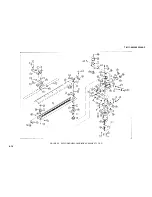
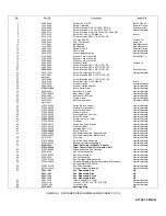
Page 6-11, Figure 6-2, items 47 and 48 part no.'s are:
47 Block, Pen Arm, 07034-60320; 48 Pen Scale Assy - Eng,
07034-60210 and Pen Scale Assy - Met - 07034-60200
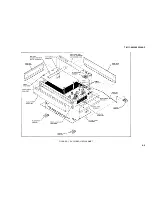
Page 6-9, Figure 6-1, make the following changes:
Pen Scale - Eng, 07034-60210; Pen Scale - Met, 07034-
60200; Rear Hood Assy - Eng, 07035-62570; Rear Hood - Met,
07035-62571; Panel Rear, 07035-00061; Panel RH, 07035-
00071; Rear Corner - RH, 07035-40030; Front Corner - RH,
07035-20150; Rear Corner - LH, 07035-40040; Panel - Front,
07035-00061; Front Corner - LH, 07035-40021; and Panel -
LH, 07035-00071.
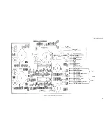
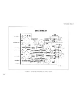
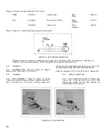
Page 7-9, Figure 7-2, use the following Component ID
illustration:
8-1
Summary of Contents for HP-7035B
Page 1: ...TECHNICAL MANUAL HEWLETT PACKARD MODEL HP 7035B ...
Page 9: ...FIGURE 1 4 DIMENSION DRAWING FIGURE 1 5 ACCESSORIES 1 3 ...
Page 12: ...FIGURE 1 7 TYPICAL FREQUENCY RESPONSE INPUT FILTER FIGURE 1 8 TYPICAL DYNAMIC RESPONSE 1 6 ...
Page 14: ...FIGURE 2 1 WING BRACKET INSTALLATION FIGURE 2 2 STACKED CONFIGURATION 2 2 ...
Page 16: ...FIGURE 3 1 FRONT PANEL CONTROLS 7035B AND 7035B 001 MODELS 3 2 ...
Page 20: ...FIGURE 4 1 BLOCK DIAGRAM FIGURE 4 2 DETAILED BLOCK DIAGRAM 4 2 ...
Page 48: ...TM 11 6625 2850 14 P FIGURE 6 1 EXPLODED VIEW CABINET 6 9 ...
Page 49: ...TM 11 6625 2850 14 P FIGURE 6 2 EXPLODED VIEW CARRIAGE ARM SHEET 1 OF 2 6 10 ...
Page 58: ...FIGURE 7 1 COMPONENT IDENTIFICATION FRAME 7 8 ...
Page 59: ...TM 11 6625 2850 14 P Figure 7 2 Component Identification Circuit Board 7 9 ...
Page 60: ...TM 11 6625 2850 14 P Figure 7 3 Schematic Model 7035B D 07035 92550 7 10 ...
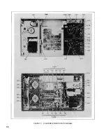
Page 62: ...TM 11 6625 2850 14 P FIGURE 8 1 COMPONENT IDENTIFICATION CIRCUIT BOARD 8 2 ...
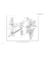
Page 66: ...TM 11 6625 2850 14 P FIGURE 8 5 EXPLODED VIEW CARRIAGE ARM 8 6 ...

