SECTION IV
THEORY OF OPERATION
4-1.
GENERAL OPERATION DESCRIPTION
4-2.
GUARDED INPUTS. The Model 7035B is equipped
with guarded inputs to enable high common mode rejection of
100 db for ac and 130 db for dc voltages. A guard shield
encloses the critical input circuitry except for the balance
potentiometer which is shielded individually from external
coupling. The guard shields are connected to the guard
terminals.
4-3.
SERVOMECHANISM. There are two similar, but
independent, self-balancing servomechanisms in the 7035B,
both isolated from ground. In operation, one servomechanism
moves the pen carriage in a vertical direction, the other moves
the entire carriage arm in a horizontal direction in response to
input signals representing data applied to the respective input
terminals. The resulting relative motions of the two
servomechanisms trace cartesian coordinate graphs of the
relationship on the graph paper.
4-4.
FIXED AND VERNIER RANGE OPERATION. The
basic dc voltage range of the servo systems is 1 millivolt per
inch (0.4 mv/cm). Operation with greater voltages is obtained
by switching precision resistors into the attenuator circuits.
Each range step may be made continuously variable by
switching in a variable potentiometer. Adjustment of this
control will allow an arbitrary voltage to drive the pen to full
scale. In operation, the initial range setting is based on the
expected maximum voltages.
4-5.
BALANCING ACTION. After passing through the
attenuator, the input signal is applied to the balance circuit
where it is cancelled by an internally supplied opposing
voltage. Under "balanced" conditions, there is no error signal
output from the balance circuit and the servo system is at null.
When the input signal changes value, an unbalanced condition
exists. The resulting error signal is applied to a photochopper
which converts the dc to a 60 Hz ac form which is amplified
and applied to the servomotor. Because the motor and
rebalance potentiometer are mechanically coupled, the
balance voltage changes value until the input signal is
cancelled. If the input data is constantly varying at rates within
the capabilities of the instrument, this rebalancing action is
continuous, and the rebalance potentiometers and the pens
are always in a position directly proportional to the amplitude of
the signals at the respective input terminals.
4-6.
AUTOGRIP HOLDDOWN. The AUTOGRIP holddown
platen is completely electronic. There are no mechanical or
moving parts. The unit is maintenance free, except for periodic
cleaning of the writing surface.
4-7.
CIRCUIT DESCRIPTION
4-8.
Schematic symbols refer to the Y-axis unless otherwise
stipulated; however, the X-axis is electrically identical to the Y-
axis (with exceptions noted). Reference should be made to the
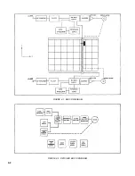
block diagrams, Figures 4-1 and 4-2, and also the schematics
referenced in each of the following paragraphs.
4-9.
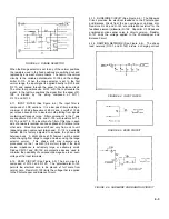
RANGE SELECTOR CIRCUIT (See Figure 4-3). Input
terminals of each axis connect to a precision step attenuator
which determines the maximum allowable input voltage. The
resistors forming the attenuator are R-101 through R-105. The
attenuator consists of five precision (
±
0.1%) metal film
resistors with good temperature stability. With the selector
switch in the 1 mv/inch (0.4 mv/cm) position, the input voltage
is applied directly to the balance circuit with no attenuation.
The attenuator is also disconnected as a shunt from the input
terminals allowing potentiometric operation in this position.
This provides essentially infinite input impedance when the
recorder is at null. Typical input currents at null on this range
are approximately 10
-10
amps. The full scale balance voltage is
always 7 mv for the Y-axis and 10 mv for the X-axis. For
higher ranges, resistance is inserted in series with the 10,000
ohms (R-109) at the base of the attenuator. On the 1 volt/inch
(0.4 mv/cm) position, and above, the 10,000 ohms is shunted
and no additional series resistance is added.
4-10. RANGE SELECTOR VERNIER CIRCUIT (See
Figure 4-3). The 10 position Range selector has 5 calibrated
positions and 5 positions that provide a vernier sensitivity that
can be adjusted by the user.
4-1
Summary of Contents for HP-7035B
Page 1: ...TECHNICAL MANUAL HEWLETT PACKARD MODEL HP 7035B ...
Page 9: ...FIGURE 1 4 DIMENSION DRAWING FIGURE 1 5 ACCESSORIES 1 3 ...
Page 12: ...FIGURE 1 7 TYPICAL FREQUENCY RESPONSE INPUT FILTER FIGURE 1 8 TYPICAL DYNAMIC RESPONSE 1 6 ...
Page 14: ...FIGURE 2 1 WING BRACKET INSTALLATION FIGURE 2 2 STACKED CONFIGURATION 2 2 ...
Page 16: ...FIGURE 3 1 FRONT PANEL CONTROLS 7035B AND 7035B 001 MODELS 3 2 ...
Page 20: ...FIGURE 4 1 BLOCK DIAGRAM FIGURE 4 2 DETAILED BLOCK DIAGRAM 4 2 ...
Page 48: ...TM 11 6625 2850 14 P FIGURE 6 1 EXPLODED VIEW CABINET 6 9 ...
Page 49: ...TM 11 6625 2850 14 P FIGURE 6 2 EXPLODED VIEW CARRIAGE ARM SHEET 1 OF 2 6 10 ...
Page 58: ...FIGURE 7 1 COMPONENT IDENTIFICATION FRAME 7 8 ...
Page 59: ...TM 11 6625 2850 14 P Figure 7 2 Component Identification Circuit Board 7 9 ...
Page 60: ...TM 11 6625 2850 14 P Figure 7 3 Schematic Model 7035B D 07035 92550 7 10 ...
Page 62: ...TM 11 6625 2850 14 P FIGURE 8 1 COMPONENT IDENTIFICATION CIRCUIT BOARD 8 2 ...
Page 66: ...TM 11 6625 2850 14 P FIGURE 8 5 EXPLODED VIEW CARRIAGE ARM 8 6 ...

