


Installing the Control
3-29
UL
The 4286 VIP Module is not permitted in UL installations.
Detailed operating instructions for phone access to the security system are provided with the VIP Module.
The 4286 VIP Module features:
•
Allows the user to receive synthesized voice messages over the phone regarding the status of the security system.
•
Allows the user to arm and disarm the security system and perform most other commands using the telephone
keypad.
•
Allows the user to control relays using the telephone keypad.
•
Provides voice annunciation over the phone to confirm any command that is entered.
•
Announces many of the same words that would normally be displayed on an alpha keypad under the same system
conditions. Refer to the words in bold on the Alpha Vocabulary list found in the
#93 Menu Mode
in the
Programming Guide
.
•
Can be supervised for connection to control panel (annunciated and reported as Zone 804).
The 4286 is wired between the control panel and the premises’ handset(s) (see
Figure 3-33
). It listens for TouchTones on
the phone line and reports them to the control panel. During on-premises phone access, it powers the premises phones.
During off-premises phone access, it seizes the line from the premises phones and any answering machines.
•
The VIP module will not operate until the device address (04) is enabled in the control’s
Device Programming in
#93 Menu Mode.
•
Do not mount the VIP Module on the cabinet door or attempt to attach it to the PC board.
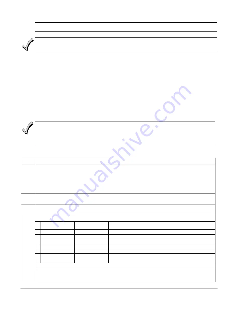
To install the VIP module, perform the following steps:
Step Action
1
Mount the module in the control cabinet if space is available or, if this is not possible, on the side of the
cabinet or adjacent to it.
If you mount the VIP Module inside the control cabinet,
attach it to the cabinet’s interior surface with
2-faced adhesive tape. You may leave the module’s cover off if it is mounted within the cabinet.
If you mount the module outside the cabinet,
use the screw holes at the rear to mount horizontally or
vertically (2-faced adhesive tape may be used, if preferred).
2
Affix the 4286 connections
label (supplied separately) to the inside of the VIP Module’s cover, if the cover is
used. Otherwise, affix the label to the inside of the
control cabinet’s
door.
3
Make 12V (+) and (–) and data-in and data-out connections from the VIP Module to the control, using the
connector cable supplied with the VIP Module. These are the same connections as for remote keypads.
Connect the module to the phone line as shown below. See
Figure 3-33.
4286 Terminal
Connects to direct
connect cord:
1.
Phone In (Tip)
green wire
2.
Phone In (Ring)
red wire
3.
Phone Out (Tip)
brown wire
4.
Phone Out (Ring)
gray wire
5.
No Connection
6.
Audio Out 1
∗
Speaker
7.
Audio Out 1
∗
Speaker
∗∗∗∗
Supported by the 4286 only
4
Use an RJ31X Jack with the phone cable supplied with the control to make connections to the VIP module.
Make connections exactly as shown in
Figure 3-33
.
This is essential, even if the system is not
connected to a central station. The 4286 will not function if this is not done.
Summary of Contents for VISTA-128BPEN
Page 2: ......
Page 10: ......
Page 58: ...Vista 128BPEN Installation and Setup Guide 3 38 ...
Page 82: ...Vista 128BPEN Installation and Setup Guide 5 14 ...
Page 102: ...Vista 128BPEN Installation and Setup Guide 8 2 ...
Page 118: ...Vista 128BPEN Installation and Setup Guide C 2 ...
Page 126: ......


