EXPERION MX RAE STATION LAYOUT
6510020335
86
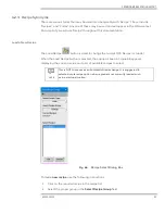
Click on Current Color Code to open
Simple Recipe Change
Pop-up.
4.
Scanner Modes:
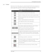
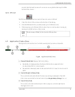
The status of the scanners is shown in the Application Status Zone of every display. In
multiple scanner systems, scanner number 1 is the closest to the wet end. Scanner
number 2 is the second closest to the wet end, and so on.
When both the scanners are scanning, the mode indicates
SCANNING 1 2
and
displays the radiation symbol to indicate that the shutter on the reel basis weight
gauge is open.
With only the breaker stack scanner, the mode indicates
SCANNING 1
and does not
display the radiation symbol because the breaker stack scanner does not have a basis
weight gauge.
With both scanners stopped, the mode indicates
OFFSHEET 1 2
.
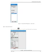
Click on this Scanner Modes to open
Scanner Control
pop-up.
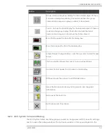
Following are the scanner modes:
•
OFFLINE
•
SCANNING
•
OFFSHEET
•
STANDARDIZE
•
BACKGROUND
•
SINGLE POINT and MAINTENANCE
OFFLINE
indicates that the scanner has been taken offsheet by the local scanner control
buttons. Scanning must be re-started with the same scan control buttons on the scanner
frame. This is a safety feature, which alerts any personnel in the vicinity of the scanner that
the heads are about to resume scanning before pressing the
SCAN
button at the scanner.
OFFSHEET
occurs automatically on a paper break. It also occurs when you send the
sensor heads off the sheet using the operator console.
STANDARDIZE
and
BACKGROUND
indicates that the scanner is being recalibrated. The scanner
automatically resumes scanning shortly.
SINGLE POINT
indicates the scanner is reading a specific position on the sheet. This is an
operator-initiated action accessible through the scanner control display (see Figure 73).
MAINTENANCE
indicates that maintenance personnel are performing maintenance tasks
on the scanner.
Summary of Contents for Experion MX
Page 1: ...Experion MX RELEASE 702 1 Operators Guide 6510020335 Rev 02 May 2019 ...
Page 7: ...6510020335 7 8 NOTICES 168 ...
Page 20: ...SCANNER SAFETY AND LOCAL CONTROLS 6510020335 20 Fig 15 Cable End Voltage Zones ...
Page 21: ...SCANNER SAFETY AND LOCAL CONTROLS 6510020335 21 Fig 16 Distant End Voltage Zones ...
Page 124: ...PROCESS INFORMATION DISPLAYS 6510020335 124 Fig 105 Profile Display ...
Page 159: ...PROCESS INFORMATION DISPLAYS 6510020335 159 Fig 148 Precision Platform 4000 01 Scanner ...
Page 160: ...PROCESS INFORMATION DISPLAYS 6510020335 160 Fig 149 Precision Platform 4000 20 21 Scanner ...


