SCANNER SAFETY AND LOCAL CONTROLS
6510020335
50
When the keyswitch is turned off, the yellow indicator is not lit, and sensors associated with
that hazard type are not enabled when the icon/button is pressed.
Purpose:
The sensor key lock allows for LOTO of sensors, enabling safe work to be conducted near
the scanner head and sensors in accordance with safety regulations.
Because the worker has control of the key, a coworker cannot inadvertently reenable
hazardous sensors.
2.3.3.4 Sensor Enable
Description:
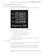
The user panel provides individual sensor-enable and -disable control for sensors
associated with radiation, eye safety, and sheet contact hazards (see Figure 50). Sensors
that do not fall under one of these hazard conditions are not represented on the panel, for
example, infrared and camera-based sensors.
Fig. 50.
Sensor Enable Hazard Groups
Pressing the icon/button on the user panel causes the icon to be lit. If all safety conditions
are satisfied, the icon remains lit and the sensor is available for automated control by the
computer system. If an error condition exists, the icon will not stay lit.
Purpose:
The sensor enables buttons to allow for individual sensors to be temporarily disabled and
enabled at the scanner. Operators can control sensor operation while on the machine floor
without needing to go back to the host computer screens.
2.3.3.4 Head alignment interlock (head split switch)
Description:
To ensure that the upper and lower head are in rough alignment proximity, a magnet and
limit switch arrangement is employed in the opposing sheet guide assemblies, so the limit
switch will open if one head is moved further than 25 mm (0.98 in) from the other. The
Summary of Contents for Experion MX
Page 1: ...Experion MX RELEASE 702 1 Operators Guide 6510020335 Rev 02 May 2019 ...
Page 7: ...6510020335 7 8 NOTICES 168 ...
Page 20: ...SCANNER SAFETY AND LOCAL CONTROLS 6510020335 20 Fig 15 Cable End Voltage Zones ...
Page 21: ...SCANNER SAFETY AND LOCAL CONTROLS 6510020335 21 Fig 16 Distant End Voltage Zones ...
Page 124: ...PROCESS INFORMATION DISPLAYS 6510020335 124 Fig 105 Profile Display ...
Page 159: ...PROCESS INFORMATION DISPLAYS 6510020335 159 Fig 148 Precision Platform 4000 01 Scanner ...
Page 160: ...PROCESS INFORMATION DISPLAYS 6510020335 160 Fig 149 Precision Platform 4000 20 21 Scanner ...


