SCANNER SAFETY AND LOCAL CONTROLS
6510020335
69
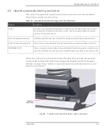
Fig. 59.
Motion Control Switch Locations
2.5.1
Preset Switch
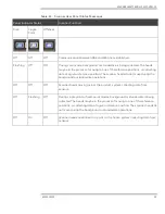
The preset switch provides a reference position to the FC when the head scans. The preset
switch is located approximately mid-scanner on the upper track. When the heads pass, the
preset switch is activated with a magnet in the head carriage, and a digital signal is sent to
the FC input in the cable end.
The preset switch signal is used by the FC electronics to monitor and correct for errors in
actual head position versus encoder count.
2.5.2
Limit Switches
A limit switch is located at each end of the upper head carriage track, inside of the crash
switch locations. The motion controller is typically set to reverse the direction of the heads
before they reach either switch.
If the heads pass by a limit switch, a magnet on the carriage will activate the switch,
sending a digital signal to an FC input in the cable end. In response, the FC disables the
motor drive signal for the direction the head was being driven. A reversal of drive direction,
either in scan mode or in manual mode, will bring the heads back inside the area between
the limit switches.
2.5.3
Crash Switches
A crash switch is located at each end of the lower head carriage track. These switches
notify the system if the head has overrun a crash switch and is about to come into contact
with the buffer stops (shock absorbers) mounted to each end of the scanner frame.
2.5.4
Over Temperature Protection
Description:
Over-temperature protection is provided through the use of:
•
Temperature reporting from upper and lower heads.
Summary of Contents for Experion MX
Page 1: ...Experion MX RELEASE 702 1 Operators Guide 6510020335 Rev 02 May 2019 ...
Page 7: ...6510020335 7 8 NOTICES 168 ...
Page 20: ...SCANNER SAFETY AND LOCAL CONTROLS 6510020335 20 Fig 15 Cable End Voltage Zones ...
Page 21: ...SCANNER SAFETY AND LOCAL CONTROLS 6510020335 21 Fig 16 Distant End Voltage Zones ...
Page 124: ...PROCESS INFORMATION DISPLAYS 6510020335 124 Fig 105 Profile Display ...
Page 159: ...PROCESS INFORMATION DISPLAYS 6510020335 159 Fig 148 Precision Platform 4000 01 Scanner ...
Page 160: ...PROCESS INFORMATION DISPLAYS 6510020335 160 Fig 149 Precision Platform 4000 20 21 Scanner ...


