Page 52
1 Dec 2003
34-45-4
7
MAINTENANCE MANUAL
CAS-100 COLLISION AVOIDANCE SYSTEM
Use or disclosure of information on this page is subject to the restrictions in the proprietary notice of this document.
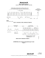
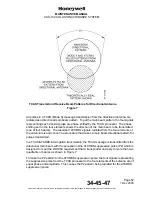
TCAS Transmit and Receive Beam Patterns for Directional Antenna
Figure 7
All pulses in a TCAS (Mode S) message transmission from the directional antenna are
radiated as a directional main beam pattern. To get the main beam pattern, the four signals
representing each transmit pulse are phase shifted by the TCAS processor. The phase
shifting set on the four elements shows the direction of the main beam to be transmitted
(one of four beams). The resultant 1030 MHz signals radiated from the four elements of
the antenna mix and cancel in a procedure that makes a main beam directional pattern for
pulses transmitted.
In a TCAS/ATCRBS interrogation transmission, the TCAS message is transmitted from the
directional main beam with the exception of the ATCRBS suppression pulse (P2) which is
designed to meet the DO185A requirement that a transponder not reply to more than two
quadrants or beams as shown in Figure
7.
To make the P2 pattern for the ATCRBS suppression pulse, the four signals representing
the suppression pulse from the TCAS processor to the four elements of the antenna are of
equal phase and amplitude. This causes the P2 pattern being radiated for the ATCRBS
suppression pulse.


