Page 1030
1 Dec 2003
34-45-4
7
MAINTENANCE MANUAL
CAS-100 COLLISION AVOIDANCE SYSTEM
Use or disclosure of information on this page is subject to the restrictions in the proprietary notice of this document.
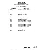
Table 1008. Discrete Pin Numbers
(cont)
NOTE:
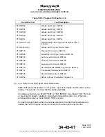
Advisory Inhibit and TCAS Mode Data is shown in
Table 1009.
Discrete Pin
Number
Display Text
Discrete Description
RMP5K
Air/Ground 1
The Air/Ground Discrete Input for the Air/Ground relay.
The normal failure mode is the airborne condition.
The following applies:
RMP5K RTP5J Definition
1 1 a/c on ground, don’t inhibit ATCRBS replies
1 0 a/c on ground, don’t inhibit ATCRBS replies
0 1 a/c on ground, inhibit ATCRBS replies
0 1 a/c airborne, don’t inhibit ATCRBS replies
Where 0 = Open
1 = Ground
RMP6D
Performance Limit
The performance limit shows to TCAS when the
aircraft can no longer get a 1500 feet per minute climb.
When the input is GROUND the performance is not
limited. When the input is OPEN the climb is limited if
the altitude of the aircraft is above the value set by the
Altitude Limit Program (See below).
Limit Input RMP6D Relative Altitude Climb Limited
Yes Open Below No
Yes Open Above Yes
No Gnd Below No
No Gnd Above No
RMP7E
TA Display No. 1 Status
The TA Display Status input are connected to their
related Traffic Display Status output (valid).
RMP7J
TA Display No. 2 Status
If any of the Display Status discretes are not
necessary they must be attached to ground as
necessary for the installation.
RMP14C
RA Display No. 1 Status
The RA Display 1 and 2 Status discretes indicate the
validity of the resolution displays. They are connected
to their respective RA Display Status output (valid).
RMP13E
RA Display No. 2 Status
RMP13F
Landing Gear
This pin shows the position of the landing gear. The
usual mode is the RETRACTED position.
Where 0 = Gear Retracted = Open
1 = Gear Extended = Ground


