


MAINTENANCE MANUAL
CAS-100 COLLISION AVOIDANCE SYSTEM
Page 99
1 Dec 2003
34-45-4
7
Use or disclosure of information on this page is subject to the restrictions in the proprietary notice of this document.
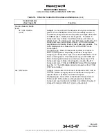
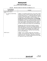
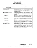
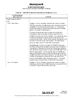
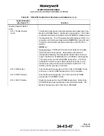
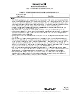
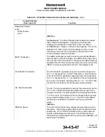
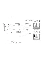
Table 20. CTA-100A Control Unit Controls and Indicators
Control/Indicator
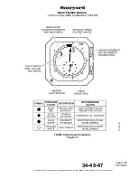
(See Figure 12)
Function
Mode Select Switch
Rotary switch. Supplies mode control for the transponders
and TCAS processor. The mode selector switch can put
the transponders into standby mode or active mode with
altitude interrogation on or off. The mode selector switch
is also used to set the TA (Traffic Advisory) or TA/RA
(Traffic Advisory/Resolution Advisory) modes for the TCAS
processor. The position of the mode selector switch finds
the correct ARINC 429 control data to transmit to the Mode
S transponders and the TCAS processor. The switch
supplies a momentary TEST position, which lets the
personnel start a TCAS system test.
(NOTE 1.)
TEST Position
The TEST mode is to start the TCAS system test. The
TEST mode position is a momentary switch position.
When the rotary switch is held in the TEST position for a
minimum of one second, the CTA-100A outputs SSM =
FUNCTIONAL TEST on all ARINC 429 labels. When the
rotary switch is released, the CTA-100A starts the previous
SSM transmission.
STANDBY Position
The Standby/On discrete output for transponder No. 1 and
transponder No. 2 are set to standby.