Page 43
1 Dec 2003
34-45-4
7
MAINTENANCE MANUAL
CAS-100 COLLISION AVOIDANCE SYSTEM
Use or disclosure of information on this page is subject to the restrictions in the proprietary notice of this document.
(k)
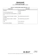
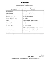
Five discrete input from RA/TA Intruder Display Limit straps. These straps
determine the maximum number of aircraft that can be shown on the traffic display
(from 1 to 30).
(l)
Discrete input from Ground Display Mode strap. This input determines if the traffic
is shown when own aircraft is on-the-ground.
(m) Discrete input from RA/TA Display All Traffic Mode strap. This input determines if
all targets are shown at all times or when an RA or TA is present.
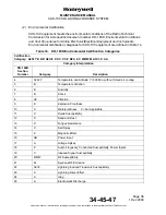
(n) Continuity/resistance checks on the top and bottom TCAS antenna ports. This data
lets the TCAS processor find if an omni or directional antenna is used as the bottom
TCAS antenna. The data also lets the processor find if the antenna cables are
correctly connected to the top and the bottom antennas. The four ports for each
directional antenna must reflect special and different resistance values because of
port identification resistors attached in the directional antenna.
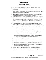
(o) System validity inputs. If a failure is found on any of the following input, TCAS
supplies the failure annunciation data to the resolution advisory and traffic displays.
1 Discrete failure status input from the TA/VSI units, RA/VSI units, or other optional
display units.
NOTE:
In the event of a display unit failure, the display sets its display valid
output discrete to invalid and tries to show status of the fault found. The
fault is shown if the properties of the fault allow (for example, specific
faults cause a blank display and do not allow the display of data).
NOTE:
Loss
of a TA/VSI will be reported on the maintenance bus.
NOTE:
The TCAS processor will automatically go into the standby mode if both
radio altimeters, both RA/VSI units, or both TA/VSI units fail.
2 Loss of continuity through the TCAS antennas.
3 Failure status data or loss of data on the ARINC 429 data link from the Mode S
transponder.
4 Internal TCAS processor failures that include failure of internal power supplies.
5 Incorrect data from the radio altimeter if one is connected, or incorrect data from
both radio altimeters if two are connected.
(p) The TCAS processor stops all TCAS processing and shows an applicable
annunciation on the display units if a particular failure decreases the TCAS
operation. TCAS processor self-tests and failure annunciations are given in the
MAINTENANCE PRACTICES and FAULT ISOLATION sections of this manual.

