Page 95
1 Dec 2003
34-45-4
7
MAINTENANCE MANUAL
CAS-100 COLLISION AVOIDANCE SYSTEM
Use or disclosure of information on this page is subject to the restrictions in the proprietary notice of this document.
Table 19. CTA-81B Control Unit Controls and Indicators
(cont)
Control/Indicator
(See Figure 11)
Function
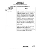
ALT SOURCE 1/2 Switch
Sets one of two barometric altimeter sources to the activated Mode
S or ATCRBS transponder. The OFF POSITION makes
unserviceable the altitude squawk (two altitude sources only).
FL Pushbutton Switch
Spring-loaded pushbutton switch. When pushed and released, the
relative altitude annunciations for the intruder aircraft are replaced
on the traffic display with flight-level altitude annunciations for a
period of 15 seconds. During the 15 second period, own aircraft
flight-level altitude also comes into view on the traffic display. After
15 seconds, own aircraft flight-level altitude goes out of view from
the display and the intruder aircraft altitude annunciations change
to relative altitude annunciations.
(NOTE 5.)
If a new RA or TA category aircraft is detected by the TCAS during
the 15 second period, the 15 second flight-level display is made
unserviceable and relative altitudes reappear.
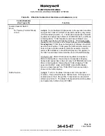
TCAS RANGE Switch
Four position rotary switch. Sets 15, 10, 5, or 3 nautical mile range
scale for the traffic display. The set display scale is shown as 15
NM, 10 NM, 5 NM, or 3 NM on the traffic display.
(NOTES 6., 7.,
and 9.)
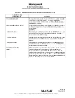
ABOVE/NORM/BELOW Switch
Three position toggle switch. Sets relative altitude display limits for
nonthreat category aircraft (open-white diamond symbols) on the
traffic display.
(NOTE 8.)
ABOVE Position
Sets display of nonthreat aircraft m8700 feet above own
aircraft and down to -2700 feet below own aircraft. ABOVE is
shown on the traffic display.


