Page 89
1 Dec 2003
34-45-4
7
MAINTENANCE MANUAL
CAS-100 COLLISION AVOIDANCE SYSTEM
Use or disclosure of information on this page is subject to the restrictions in the proprietary notice of this document.
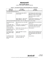
Table 18. CTA-81A Control Unit Controls and Indicators
(cont)
Control/Indicator
(See Figure 10)
Function
Code Select Knobs
Lets selection of transponder identification code. The transponder
inserts this code into replies to Mode A interrogations and Mode S
ATC identification requests from ground stations. The ATC IDENT
code is not used by TCAS.
ATC IDENT Code Display
Shows transponder ATC identification code set by the Code Select
Knobs and annunciates which transponder is selected by the ATC
1-2 Switch.
ATC FAIL
Illuminates (amber) for some failure conditions found by the Mode
S transponder (refer to TRA-67 ATC Mode S Transponder System
Maintenance Manual I.B. 1167 for the details).
NOTES:
1:
TCAS operating modes are requested from the transponder/TCAS control unit (i.e. TA/RA
mode is
requested by turning the function selector switch to TA/RA). The TCAS processor can or can not go into
the requested mode dependent on prevailing conditions. For example: If TA/RA mode is requested from
the control unit and own aircraft is below 500 feet AGL, TCAS automatically defaults to TA ONLY mode
(TCAS sensitivity level No. 2) regardless of the TA/RA mode request from the panel.
2. TCAS can be strapped to show all traffic, all the time or when a TA or RA is present.
3. If own aircraft is below 500 feet AGL, TCAS defaults to TA ONLY mode.
4. Holding the FL switch pushed for longer than 15 seconds will not show flight level altitudes for longer than
15 seconds.
5. The range at which resolution or traffic advisories are generated by TCAS is unaffected by the TCAS
RANGE switch.
6. The presence of intruder aircraft categorized RA or TA that are more than the set display range is indicated
by 1/2 target symbols at the edge of the screen. An RA OFF scale or TA OFF scale annunciation on the
traffic display is shown. The position of the 1/2 symbol shows the approximate bearing of the intruder.
The 1/2 symbol color and shape shows if the off-scale intruder is an RA or TA (1/2 red square for off-scale
RA; 1/2 yellow circle for off-scale TA). When this occurs, the aircraft symbol can be shown by increasing
the set range on the TCAS RANGE switch.
7. RA, TA, and proximity category aircraft displays are inaffected by the ABOVE/NORM/BELOW switch (RA
and TA aircraft in +8700 feet of own aircraft are shown regardless of the ABOVE/NORM/BELOW switch
position. Proximity category aircraft are always in +1200 feet altitude of own aircraft).
8. TCAS RANGE switch is not supplied on all versions of the CTA-81A. When a PPI, TA/VSI, or dedicated
traffic display having optional range selectors is used, range selection is made at the traffic display. Other
versions have range selections to 40 nautical miles.


