194
........ ..
iii-1
M4x8 (4x)
iii-2
iii-3
4
2
3
1
5
Installation
iii Installation procedures
Unit:
Refer to the drawing in i section for correct wheel bal-
ancer positioning. If the wheel balancer needs secur-
ing, we recommend fixing elements with a diameter of
8 mm, quality 8.8 or higher.
Supports for Accessories:
•
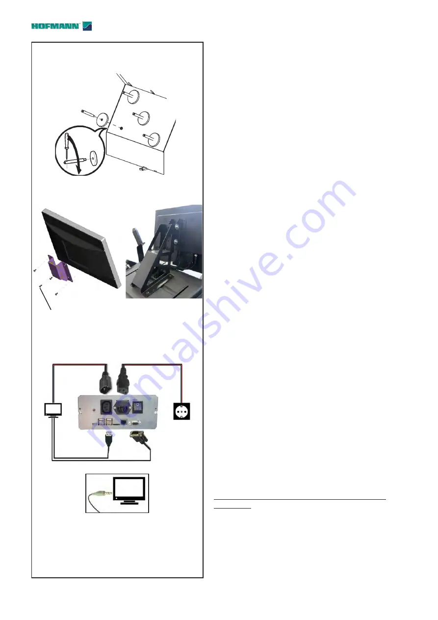
Unpack the 4 threaded accessory support studs
and the support plates.
•
Refer to
Figure iii-1
. Fit the 4 threaded accessory
support studs and the plates.
Clamping devices:
•
Put the clamping devices on the accessory support
pins and in the appropriate housings.
Fitting and connecting the monitor
Fig. iii-2 VESA support
The 4 screws needed (M4x8) to fix the VESA support
to the monitor are part of the kit supplied.
Fix the VESA support to the monitor.
Figure iii-3 Connection of monitor and PC
Warning
Before connecting any cable turn off the mains switch.
Plug in the plug (
1,Fig.iii-3
) of the power supply
cable.
Insert the monitor plug (
2
) in the connection socket
(VGA) of the built-in unit.
Insert the USB connector (
3
) into the PC and the
monitor.
Insert the monitor connector. (
4
), into the monitor
socket.
Insert the audio jack (
5
) in the monitor socket.
Note:
The warning beeps from the machine cannot
be heard if the audio cable (
5
) is not
connected.
iv Test procedures
•
Balance a wheel to less than a 0.25 oz. (5 grams)
unbalance per plane.
•
Perform a User Calibration,
6.2.
v Instructing the operator
(Following applies only if a unit is installed by a service
Technician)
•
Show and explain the Safety Booklet.
•
Show the user how to switch the unit on and off.
•
Show the operator how to perform an emergency
stop.
•
Show the operator how to select a wheel type, enter
data and apply a weight.
Summary of Contents for Geodyna 8200 Series
Page 188: ...188 Blank Page ...


