Rev. 3.0, 10/02, page 619 of 686
driven high, a transition is made to the program execution state via the reset exception handling
state.
22.5.3
Hardware Standby Mode Timing
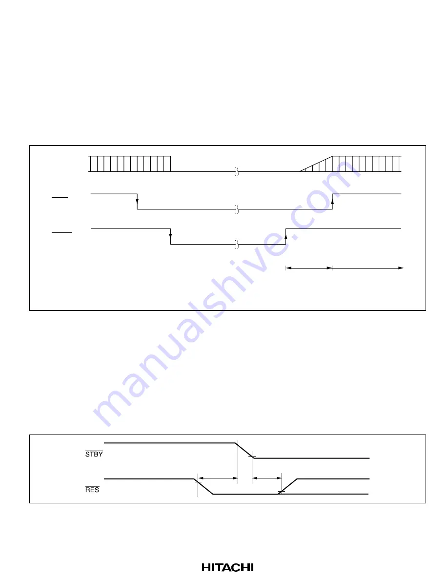
Figure 22.4 shows an example of hardware standby mode timing.
When the
STBY
pin is driven low after the
RES
pin has been driven low, a transition is made to
hardware standby mode. Hardware standby mode is cleared by driving the
STBY
pin high, waiting
for the oscillation stabilization time, then changing the
RES
pin from low to high.
Oscillator
RES
STBY
Oscillation
stabilization
time t
OSC1
Reset exception
handling
Figure 22.4 Hardware Standby Mode Timing (Example)
22.5.4
Hardware Standby Mode Timings
Timing of Transition to Hardware Standby Mode
1. To retain RAM contents with the RAME bit set to 1 in SYSCR
Drive the
RES
signal low at least 10 states before the
STBY
signal goes low, as shown in
figure 22.5. After
STBY
has gone low,
RES
has to wait for at least 0 ns before becoming high.
t
2
≥
0ns
t
1
≥
10t
cyc
Figure 22.5 Timing of Transition to Hardware Standby Mode
Summary of Contents for H8S/2215 Series
Page 4: ...Rev 3 0 10 02 page iv of lviii ...
Page 6: ...Rev 3 0 10 02 page vi of lviii ...
Page 28: ...Rev 3 0 10 02 page xxviii of lviii ...
Page 122: ...Rev 3 0 10 02 page 64 of 686 ...
Page 132: ...Rev 3 0 10 02 page 74 of 686 ...
Page 156: ...Rev 3 0 10 02 page 98 of 686 ...
Page 198: ...Rev 3 0 10 02 page 140 of 686 ...
Page 320: ...Rev 3 0 10 02 page 262 of 686 ...
Page 384: ...Rev 3 0 10 02 page 326 of 686 ...
Page 474: ...Rev 3 0 10 02 page 416 of 686 ...
Page 608: ...Rev 3 0 10 02 page 550 of 686 ...
Page 614: ...Rev 3 0 10 02 page 556 of 686 ...
Page 650: ...Rev 3 0 10 02 page 592 of 686 ...
Page 652: ...Rev 3 0 10 02 page 594 of 686 ...
Page 680: ...Rev 3 0 10 02 page 622 of 686 ...
Page 732: ...Rev 3 0 10 02 page 674 of 686 ...
Page 740: ...Rev 3 0 10 02 page 682 of 686 ...


