d) Slowly slide the enclosure forward to ensure the CMA arm is operating properly and return it back to
its proper location.
7.
Cable the CMA.
a) Unlatch the elbow side of the CMA arm and swing it forward by pressing the blue button that says
“push” to unlatch it and swing it out.
b) Gather the cables, two power cables and one Ethernet cable to install in this right hand side.
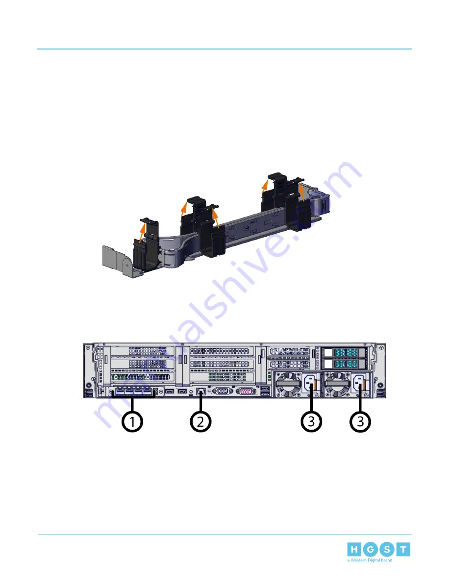
c) Open all of the baskets.
Figure 36: Open Baskets
d) Connect the power cords and cables to the enclosure.
Figure 37: Standard Power Cord and Cable Connections
e) Close all of the baskets.
f) Reconnect the CMA at the elbow to connector A.
8.
Test for binding in the extension of the CMA by gently pulling the enclosure out of the rack to ensure the
cables extend properly and that the system doesn’t bind at all. If it does, examine the point at which the
binding occurred and adjust the seating of cables in the baskets, check the connections to the rails, and
examine the joints of the CMA arm to ensure that they are all functioning properly.
9.
Make sure the CMA is in operational position by folding the arm in toward the enclosure and attaching
the elbow end of the CMA to the connector that is attached to the rail.
10. Power on the enclosure.
47
3
Part Replacement
User Guide
3.3
CMA Replacement


