DPO6000, MPO6000 Series Digital Fluorescent Oscilloscope Product Manual V1.3
36
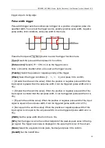
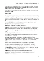
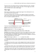
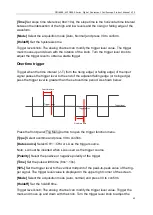
displays or blank screens into meaningful waveforms. Here are some basic concepts of
triggers.
Trigger source
Press the data source in the Trig Menu-> in the trigger control area on the front panel
to select the required trigger data source. Analog channels CH1-CH4, digital channels
D1.0-D1.3, D2.0-D2.3, D3.0-D3.3, D4.0-D4.3 can all be used as trigger data sources.
➢
Analog channel input:
The input signals of analog channels CH1-CH4 can all be used as trigger data sources.
If the selected trigger source channel is not turned on, it is regarded as an invalid trig-
ger.
➢
Digital channel input:
Only the digital channel connected to the oscilloscope can be used as the trigger data
source. [Some trigger methods cannot be selected-such as slope, video, window, under
Amp, etc.].
Acquisition process
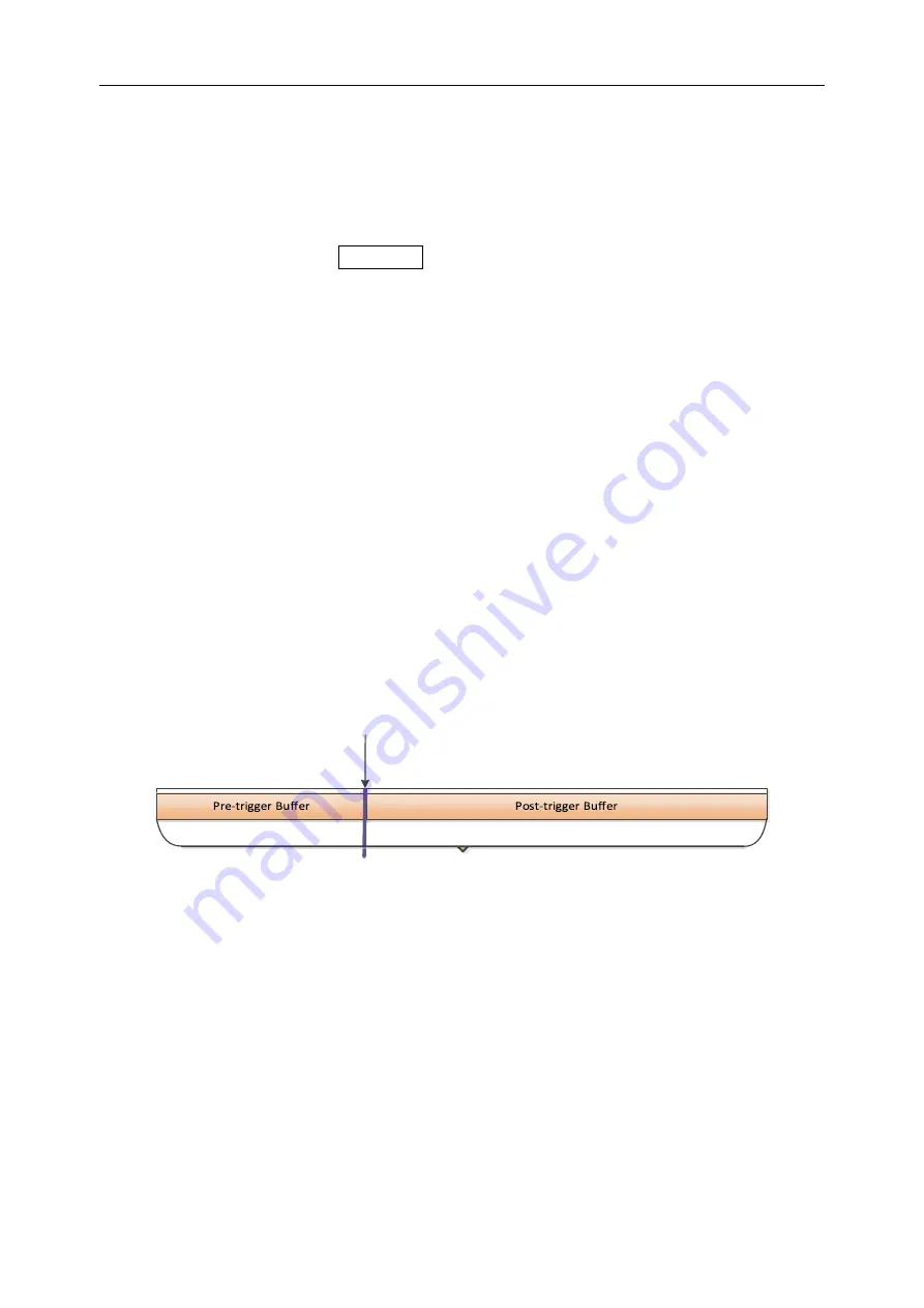
The following is a schematic diagram of the acquisition process. To facilitate under-
standing of trigger events, the acquisition memory can be divided into pre-trigger
memory and post-trigger memory.
Trigger Event
Waveform acquisition storage area
After the oscilloscope starts running, the oscilloscope stores the acquired data in the
trigger memory area. After the acquisition is completed, the oscilloscope will start to
search for trigger conditions; during the search for the trigger, the data collected by the
oscilloscope will continue to be stored in the pre-trigger storage area (new data will
continue to overwrite the existing data). Post-trigger store.
Trigger mode
Automatic mode
allows free running acquisitions without a valid trigger. This mode al-
lows untriggered sweep waveforms to occur at a time base setting of 100ms/div or
slower. When the oscilloscope detects a valid trigger condition, it completes a triggered
acquisition. When the oscilloscope detects that there is no valid trigger condition, a

