DPO6000, MPO6000 Series Digital Fluorescent Oscilloscope Product Manual V1.3
20
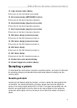
14. Logic analyzer status display
If the icon is lit, the LA channel is connected.
15. Gen3 status display [MPO6000EDU series]
If the icon is lit, the Gen3 channel is turned on.
16. Gen2 status display [signal source series]
If the icon is lit, the Gen2 channel is turned on.
17. Gen1 status display [signal source series]
If the icon is lit, the Gen1 channel is turned on.
18. CH4 status display [4-channel series]
If the icon is lit, the CH4 channel is turned on.
19. CH3 status display [4-channel series]
If the icon is lit, the CH3 channel is turned on.
20. CH2 status display
If the icon is lit, the CH2 channel is turned on.
21. CH1 status display
If the icon is lit, the CH1 channel is turned on.
22. Channel zero-scale position display
23. Channel trigger level position display
Sampling system
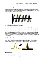
To understand the oscilloscope's waveform acquisition system, you need to understand
the sampling principle and understand the relationship between sampling rate and
memory depth.
Sampling principle
According to the Nyquist sampling principle, in order to restore the analog signal with-
out distortion, the sampling frequency should be greater than twice the highest fre-
quency in the analog signal spectrum (Fs> 2Fmax). The higher the sampling rate, the
later the recovered waveform will be closer to the original signal, but the system re-
quirements will be higher, and the conversion circuit must have a faster conversion
speed.


