DPO6000, MPO6000 Series Digital Fluorescent Oscilloscope Product Manual V1.3
71
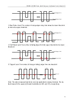
Delay and phase parameters
Signal
source A
Signal
source B
Period
FRR
FFF
FRF
FFR
LRR
LRF
LFR
LFF
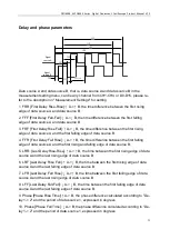
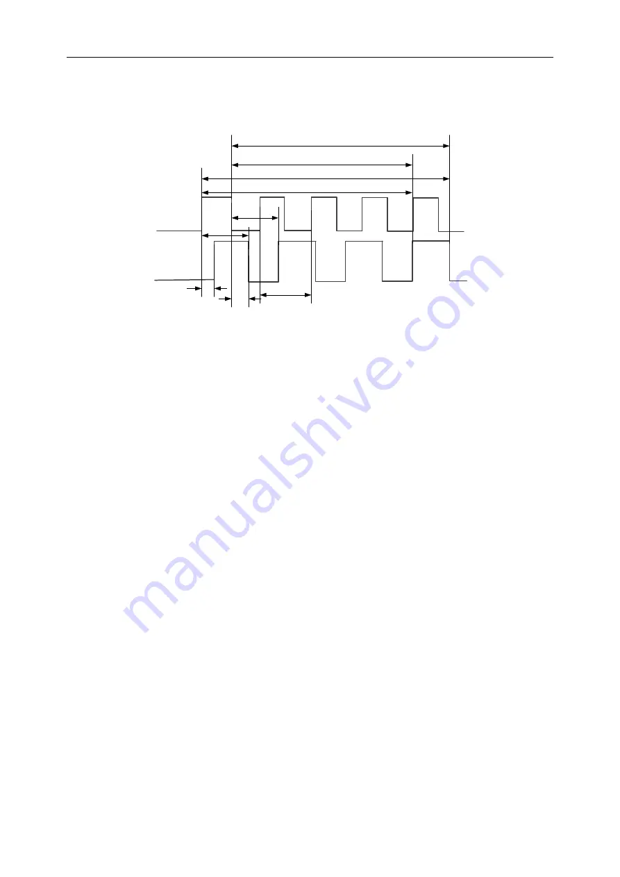
Data source A and data source B, that is, data source A and data source B in the
measurement setting menu, can be any channel from CH1-CH4 or D0-D15, please re-
fer to the description in "Measurement Settings" for setting.
1. FRR [First Delay Rise-Rise]: ↑ A-> ↑ B, the time difference between the first rising
edge of data source A and data source B.
2. FFF [First Delay Fall-Fall]: ↓ A-> ↓ B, the time difference between the first falling
edge of data source A and data source B.
3. FRF [First Delay Rise Fall]: ↑ A-> ↓ B, the time difference between the first rising
edge of data source A and the first falling edge of data source B.
4. FFR [First Delay Fall Rise]: ↓ A-> ↑ B, the time difference between the first falling
edge of data source A and the first rising and falling edge of data source B.
5. LRR: [Last Delay Rise-Rise]: ↑ A-> ↑ B, the time between the first rising edge of data
source A and the last rising edge of data source B.
6. LRF [Last Delay Rise Fall]: ↑ A-> ↓ B, the time between the first rising edge of data
source A and the last falling edge of data source B.
7. LFR [Last Delay Fall Rise]: ↓ A-> ↑ B, the time between the first falling edge of data
source A and the last rising edge of data source B.
8. LFF [Last Delay Fall-Fall]: ↓ A-> ↓ B, the time between the first falling edge of data
source A and the last falling edge of data source B.
9. Phase [Phase Rise Time]: ↑ A-> B, the phase difference calculated according to "De-
lay 1-> 2" and the period of data source 1, expressed in degrees.
10. Phase [Phase Fall Time]: ↓ A-> B, the phase difference calculated according to “De-
lay 1-> 2” and the period of data source 1, expressed in degrees.

