DPO6000, MPO6000 Series Digital Fluorescent Oscilloscope Product Manual V1.3
57
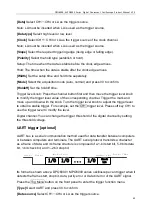
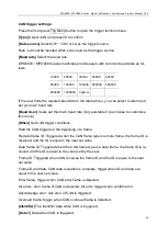
[Data 2]
Data when CAN is triggered
[Data 3]
Data when CAN is triggered
[Data 4]
Data when CAN is triggered
[Idle level]
The level value (level / high level) during the CAN frame interval. The de-
fault setting is: low level.
[Mode]
Select the acquisition mode (auto, normal) and press V0 to confirm.
[Holdoff]
Set the holdoff time.
[Decode]
Switch the decoding function.
[Label position]
The position where the decoded data is drawn on the screen (only
available when the decode function is turned on).
[Table]
Data recording mode
Trigger level knob: The analog channel can modify the trigger level value. Trigger the
mark and move up and down with the knob.
Digital channel: You can change the trigger threshold of the digital channel by setting
the threshold voltage.
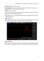
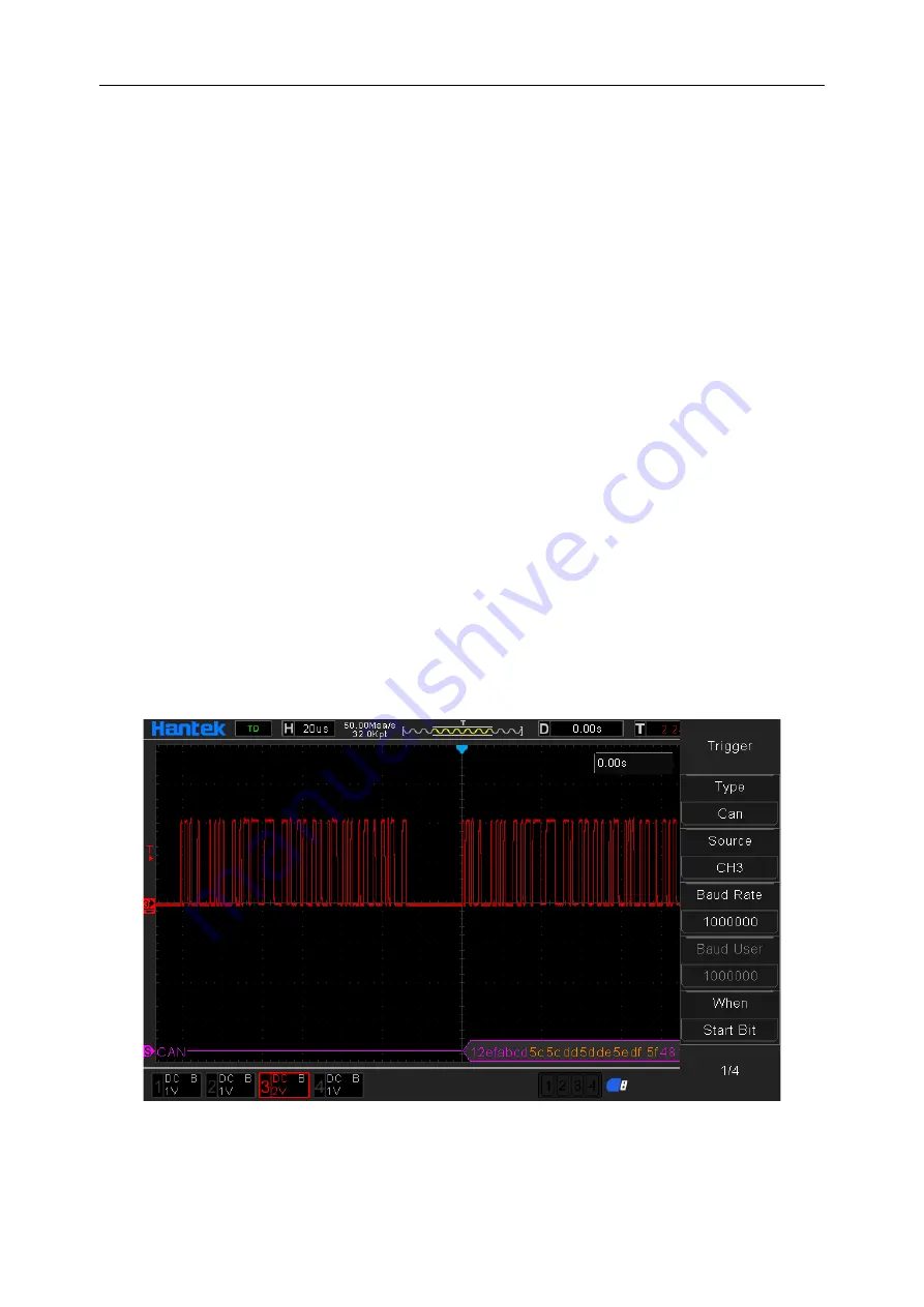
Trigger setting 1:
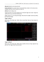
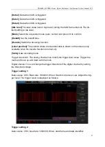
Data source: CH3; Baud rate: 1000000; When: Start bit; Idle level: Low. Adjust the trig-
ger level. The trigger result is displayed as follows:
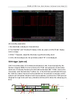
Trigger setting 2:
Data source: CH3; baud rate: 1000000; When: data frame and data; identifier:

