DPO6000, MPO6000 Series Digital Fluorescent Oscilloscope Product Manual V1.3
14
connected to a computer, users can send SCPI commands or custom programming to
control the oscilloscope through the host computer software. When the printer is con-
nected, the user prints the waveform displayed on the screen through the printer.
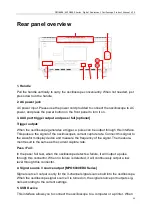
6. LAN / UART
LAN
Connect the oscilloscope to the network through this interface to remotely control it.
This oscilloscope complies with the LXI CORE 2011 DEVICE class instrument standard
and can quickly build a test system.
UART [optional]
This interface connects the oscilloscope to a control system for remote control.
7. HDMI interface [optional]
You can connect the oscilloscope to a monitor with an HDMI display through this inter-
face to get a larger display.
Front panel functions
Introduction of the main keys
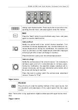
Level control system
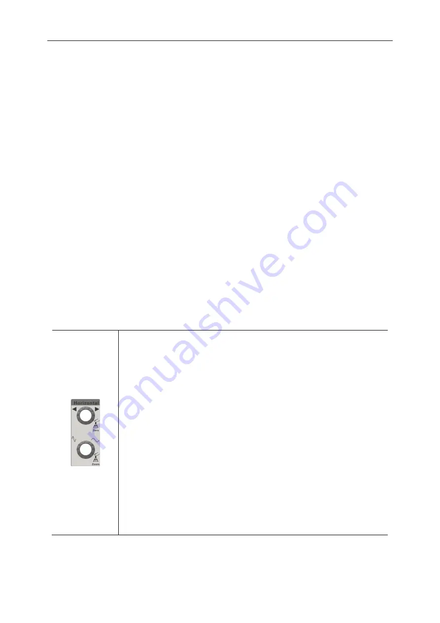
Horizontal offset:
Modify the horizontal displacement. When the knob is turned, the
trigger point moves left and right relative to the center of the
screen. During the modification, the waveforms of all channels
move left and right, and the horizontal displacement information in
the upper right corner of the screen changes in real time.
Press this knob to quickly reset the horizontal displacement.
Horizontal time base:
Modify the horizontal time base. Turn clockwise to decrease the
time base and turn counterclockwise to increase the time base.
During the modification, the waveforms of all channels are ex-
panded or compressed, and the time base information at the top
of the screen changes in real time.
Press this knob to quickly switch between single and double win-
dow display modes.
Vertical control system

