21
Subject to change without notice
V e r t i c a l s y s t e m
can be added to the signal. In order to switch this offset in the
respective soft key must be pushed. The settings window will
be backlit in blue, and the activity indicator next to the general
knob will light up; the offset can now be adjusted with the knob.
The offset voltage will be added to the signal at the vertical am
-
plifier input offsetting it by that amount from the zero position.
The possible amount of offset depends on the Volts/div setting
chosen. The offset function being activated will be indicated by
two channel markers on the left of the display, also visible if the
menu was closed. One marker indicates the position, the other
the offset (refer to Fig. 4.4). The offset is individually adjustable
for each channel.
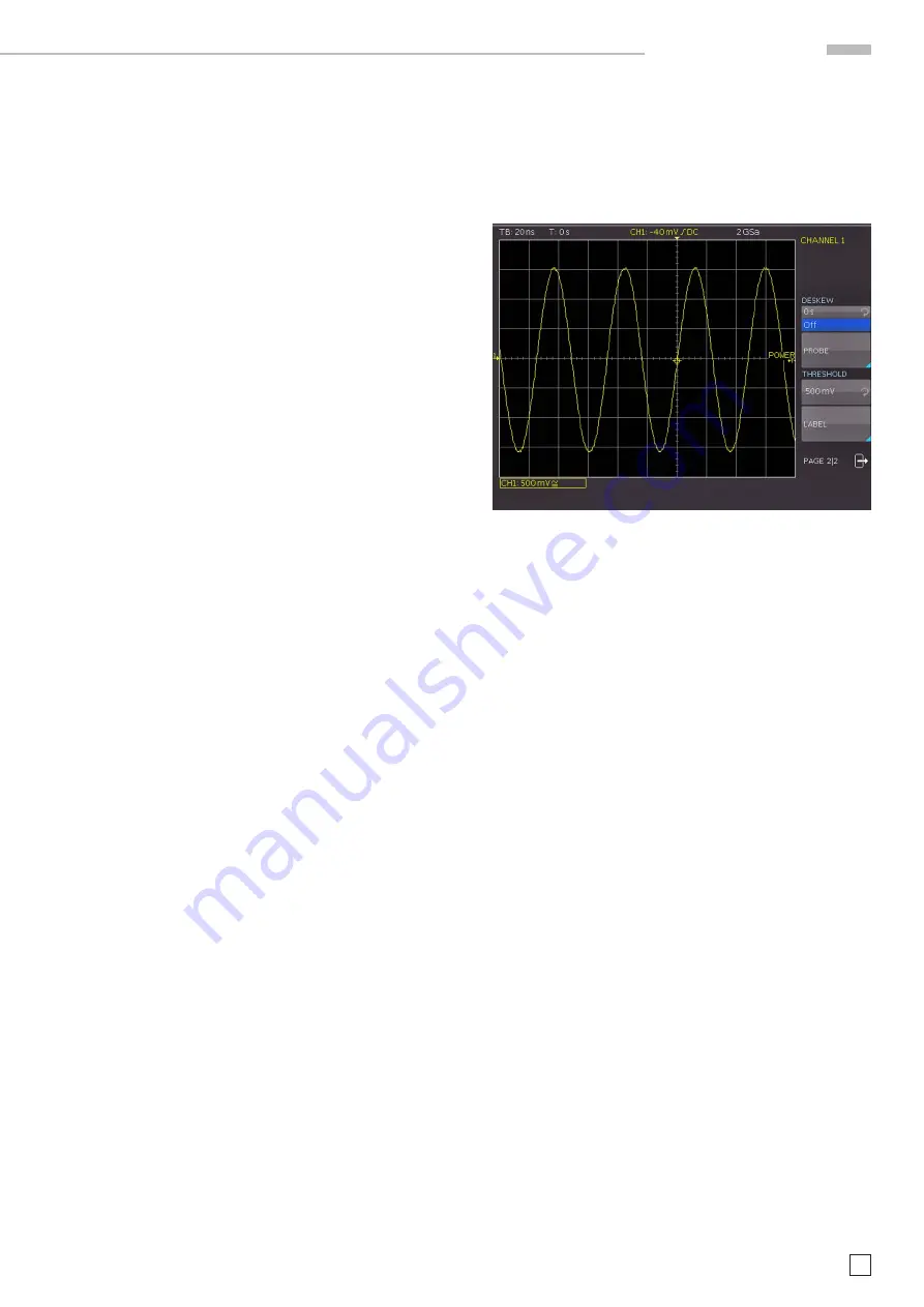
Each analog channel may also be shifted in time by ±15 ns. This
adjustment is selected in the same menu and according to the
same method as the DC offset; it is used for compensating for
the different signal delays of voltage and current probes and
different cable lengths.
4.3 Bandwidth Limit and Signal Inversion
An analog 20 MHz low pass can be inserted in the signal path
in either the short or extended menu. This will eliminate all
higher
frequency interference. The filter is activated in the
short menu by pushing the respective soft key; the information
field will be backlit in blue,
BW
will be displayed in the channel
information window.
Signal inversion is available in the short and the extended me
-
nus. If it is activated the information field will be backlit in blue,
and there will be a bar above the channel number.
4.4 Probe attenuation selection
The HZO10 or optinal HZ355 probes are recognized by the in
-
strument which automatically selects the appropriate factor.
If any other probe without automatic recognition of the attenu
-
ation
ratio or just a cable is connected to the instrument, the
attenuation factor can be set manually in the extended menu.
This is possible for x 1, x 10, x 100 x 1000 or as defined by the
user from x 0.001 to x 1000.
In addition you can select the unit Ampere in case you are using
a current probe or measure current via a shunt. If you select
A the menu shows the most common factors (1V/A, 100mV/A,
10mV/A, 1mV/A). Again you can also select any value between
defined by the user. Doing so the measurements are always
displayed with the correct unit and scale.
4.5 Level Setting
In this menu a level can be set. This level define the
threshold
for detecting a High or a Low if the analog channel are used as
source for the serial bus analysis or logic trigger. After choosing
the softmenu, the level can be set by turning the
universal knob.
4.6 Name a channel
The last entry of the channel menu open a submenu in order to
allocate a name for a channel. This name will be shown at the
display and at a print out. First of all you can switch on or off the
display of the name. Below that softmenu button you find the
soft button LIBRARY. After selecting this button you can choose
a name from several different suggestions using the universal
knob. After pushing NAME you can edit the pre-choosen name
or enter a complete new name using up to 8 characters. This
will be done by selecting the character from the virtual keypad
using turning the universal knob and selecting by pushing the
knob. Pushing the ACCEPT button switch on the name display on
the right side of the grid. The name is fixed to the channel and
will move over the screen whenever the channel will be moved.
Fig. 4.5: Threshold setting and name allocation


