48
Subject to change without notice
S e r i a l b u s a n a l y s i s
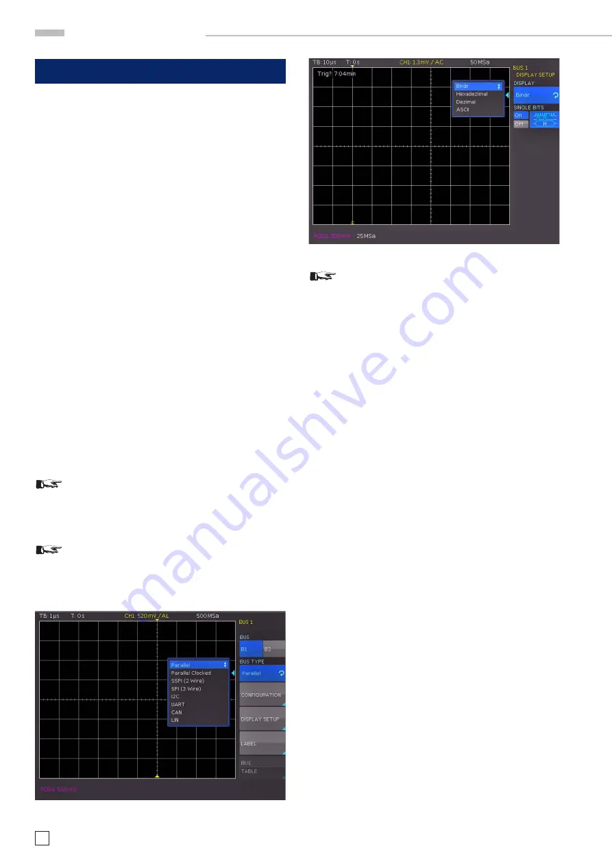
Fig. 13.2: Menu for the selection of the decoding format
13 Serial bus analysis (optional)
The HMO series can be equipped with three options to trigger
and decode serial buses.
The option HOO10 can be used to trigger and decode I
2
C, SPI
and UART/RS-232 buses on the digital channels (option
logic
probe HO3508) and on the analog inputs. This option allows the
decoding of two serial buses simultaneously.
The option HOO11 can be used to trigger and decode I
2
C, SPI
and UART/RS-232 buses on analog inputs only and it only allows
the decoding of one serial bus at a time.
The option HOO12 can be used to trigger and decode CAN and
LIN buses on the digital channels (option logic probe HO3508)
and on the analog inputs. This option allows the decoding of
two serial buses simultaneously.
The options are activated by a software licence key. This key
will either be installed at the time of manufacturing or it will be
loaded to the instrument via USB stick when the user installs
an update as described in chapter 2.10.
The analysis of parallel and serial data consists of the following
three basic steps:
– Protocol configuration
(BUS type / protocol-specific settings)
– Decoding
(Display of decoded data / Zoom / BUS table)
– Trigger
(Start / Stop / serial samples)
The serial bus analysis is performed with 1/8 of the
sampling rate.
13.1 Serial Bus Configuration
Prior to the BUS configuration it is necessary to set
the correct logic level for the digital channels (see
chapter 11.2) or the analog channels (see chapter
4.5). The default setting for both is 500 mV.
Make sure that a complete message of a serial pro-
tocol is always displayed on the screen to ensure
decoding works properly. The zoom function allows
you to view details for any specific message.
It is necessary to define a BUS before you can determine the set-
tings for the serial trigger and decoding functions. A maximum
of two buses, B1 and B2, may be defined. Press the BUS/REF
button in the VERTICAL section of the control panel. This will
open a short menu where you can press the bottom soft menu
key BU (BUS). Use the MENU button in the VERTICAL section
of the control panel and the top soft menu key to define the
respective BUS (B1 or B2).
Use the soft menu key BUS TYPE and the installed options
HOO10/HOO11/HOO12 to choose from the following BUS types:
– Parallel
Standard
– Pa Clock Standard
– SSPI (2 wire)
HOO10/HOO11
– SPI (3 wire)
HOO10/HOO11
– I
2
C HOO10/HOO11
– UART
HOO10/HOO11
– CAN
HOO12
– LIN
HOO12
The soft menu key
CONFIGURATION
allows you to invoke a
menu corresponding to the selected bus type. A menu de
-
scription can be found in the chapters of the respective BUS
configuration. The soft menu
DISPLAY SETUP
is identical for
all buses and allows you to select the decoding format.
You may choose from the following formats:
Binary, Hexadecimal, Decimal and ASCII
Use the soft menu key
BITS
to activate or deactivate the display
of individual bit lines (above the table display).
The soft menu key NAME allows you to rename a bus (see
chapter 4.6.
13.1.1 BUS Table
The soft menu
BUS TABLE
allows you to configure / export a
list of all decoded messages in storage. The table content is
protocol specific and the table display can be activated for each
individual BUS type. The top soft menu key
BUS TABLE
allows
you to activate or deactivate the list view. By default, the table
is displayed at the bottom of the screen. Generally, a complete
message of a protocol is displayed in a row. The columns include
Fig. 13.1: Bus definition menu


