56
Subject to change without notice
S e r i a l b u s a n a l y s i s
state. If you choose the hexadecimal input, the soft menu key
VALUE
and the universal knob allow you to set the value for
the respective byte. If the input is hexadecimal, only the entire
byte can be set to X. Use the soft menu key
BYTE
to toggle
between bytes.
The soft menu
IDENTIFIER AND DATA
includes the same set
-
tings as the soft menu
IDENTIFIER
. In the menu that opens
you can select the
FRAME TYPE
(general data or read data) via
top soft menu key and universal knob. In the menu
IDENTI-
FIER SETUP
below you can enter the address of the respective
pattern. The soft menu
DATA SETUP
allows you to specify the
data bit pattern or HEX values for up to 8 bytes (only available
if DATA was selected as frame type). Available comparisons
for address and data values are GREATER, EQUAL OR LESS,
EQUAL and NOT EQUAL.
Press the MENU OFF button twice or three times to close all
menus, and the oscilloscope will trigger on the set data.
13.7 LIN BUS
The LIN (Local Interconnect Network) BUS is a simple master/
slave bus system for automotive applications and is used for
the data exchange between controller units and sensors or
actuators. The signal is transmitted on one line with ground
reference to the vehicle mass. The standard data rates range
between 1.2 kBit/s and 19.2 kBit/s. A LIN message consists of
a header and the data.
A LIN BUS has the following properties:
– Serial single-wire communication protocol (byte-oriented)
– Master-slave communication (generally up to 12 knots)
– Master-controlled communication (master initiates / coor-
dinates communication)
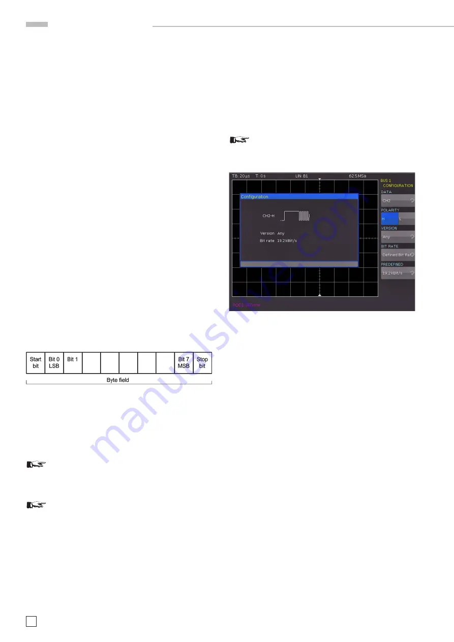
Fig. 13.23: Layout LIN byte structure
The data is transmitted in bytes without parity (based on UART).
Each byte consists of a start bit, 8 data bits and a stop bit.
13.7.1 LIN BUS Configuration
Prior to the BUS configuration it is necessary to set
the correct logic level for the digital channels (see
chapter 11.2) or the analog channels (see chapter
4.5). The default setting for both is 500 mV.
Make sure that a complete message of a serial pro-
tocol is always displayed on the screen to ensure
decoding can function properly. The Zoom function
allows you to view details for any specific message.
To decode the LIN BUS it is necessary to first determine
which channel will be connected to the data line. This setting
is selected after choosing the bus type LIN in the BUS menu
and pressing the soft menu key
CONFIGURATION
. In the
menu that opens you can press the top soft menu key
DATA
to
select the desired channel via universal knob. The soft menu
key
POLARITY
allows you to toggle between High and Low;
the active function will be highlighted in blue. An analog or a
digital channel can be connected to LIN-High or LIN-Low. You
can select any version for the LIN standard (version 1x, version
2x, J2602 or any) via soft menu key VERSION and
universal
knob. The option BIT RATE allows you to specify the number of
transmitted bits per second. You can use the
universal knob to
choose from predefined standard data rates (1.2 / 2.4 / 4.8 / 9.6
/ 10.417 and 19.2 KBit/s) and user-defined data rates (USER).
The highest possible user-defined data rate is 4MBit/s. You
can enter the user-defined value via
universal knob or numeric
input (KEYPAD button).
If LIN standard VERSION J2602 is selected, you
may only choose from the predefined standard data
rates via bottom menu item and universal knob.
Fig. 13.24: Menu for the definition of a LIN bus
13.7.2 LIN BUS Triggering
After the
BUS configuration, it will be possible to trigger on vari-
ous events. Press the
TYPE
button in the TRIGGER section of
the control panel and choose the soft menu key
SERIAL BUSES
.
Then press the
SOURCE
button in the TRIGGER section and
choose LIN. This will only be available if it was configured earlier.
Press the
FILTER
button in the TRIGGER section of the control
panel to list all available
CAN
trigger conditions.
The function
START OF FRAME
triggers on the stop bit of the
synchronizing field. The function
WAKE UP
triggers after a wake-
up frame. The soft menu
ERROR
identifies various errors in a
frame. This menu allows you to choose one or several error
message types as trigger condition:
CRC (Cyclic Redundancy Check)
LIN BUS applies a complex checksum calculation (Cyclic Re
-
dundancy Check). The transmitter calculates the CRC and trans
-
mits the result in a CRC sequence. The receiver calculates the
CRC in the same manner. A CRC error occurs if the calculated
result deviates from the received CRC sequence.
PARITY
Triggering occurs on a parity error. Parity bits are bit 6 and bit 7
of the identifier. The correct transfer of the identifier is verified.
SYNCHRONISATION
Triggering occurs if the synchronizing field indicates an error.
With the soft menu key
IDENTIFIER
you can set the trigger
to a specific identifier or a specific identifier range.
The soft
menu key
COMPARE
defines the comparison function. If the


