background image

06-1491-00-12.fm 

203

Attachments and Options

Checklist – Wet cleaning

Driving to the work site

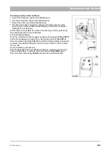
1. Start the vehicle with the ignition switch 

Fig. 113-78

.

2. As required, switch on the dipped headlight

Fig. 113-54

, working 

spotlight

Fig. 113-55

 and beacon

Fig. 113-59

.

3. Prepare the transport mode: 

Raise the front tool carrier with the joystick

Fig. 114-70

.

Bring the scrubbing deck into the transport position (vehicle symbol) 

using the locking bow

Fig. 113-A

.

4. Push the accelerator pedal

Fig. 113-36

 down slowly until the vehicle 

starts, the speed is increased further by pressing on the pedal. The 

transport mode information symbol 

Fig. 113-C

 appears in the multifunc-

tional display.

5. Slowing down or braking the vehicle: Slowly reduce the pressure on the 

accelerator pedal, the vehicle slows down or stops. The driving speed 

in the transport mode is 0 to 40 km/h.

6. At the work site, bring the locking bow

Fig. 113-A

 into the working 

position (brush symbol) and clamp it to the holder

Fig. 113-B

.

No.

Description

Reference

1

Driving to the work site

Page 203

2

Switching wet cleaning on

Page 204

3

Setting the fixed engine speed

Page 132

4

Basic and upkeep cleaning

Page 204

5

Cleaning heavily soiled surfaces

Page 205

6

Starting wet cleaning

Page 206

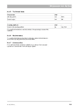
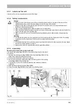
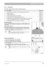
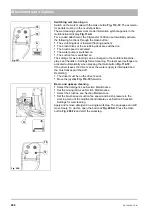
Fig. 206:

1

2

P

0

78

55

54

59

A

B

36

70

C

Summary of Contents for Citymaster 1600

Page 1: ...Citymaster 1600 1491 Operating Manual Issue 04 2016 Part number 88 10 3036 3451 01 Cleaning technology Municipal technology...

Page 2: ...es in this operating manual concerning your safety with a danger pictogram Your authorised Hako dealer is available at all times to answer further questions about the vehicle or the operating manual W...

Page 3: ...olley Lawn mowing system with the front mower Sweeping system with the front sweeping machine Snow clearing system with the front sweeping machine or a folding snow blade A roller spreader as rear att...

Page 4: ...espondence or when making a telephone query to your authorised Hako dealer or our company Vehicle type Chassis No Engine No Start up on Please enter the data applicable to your vehicle in the list abo...

Page 5: ...occurs to the vehicle resulting from the use of parts or accessories not explicitly approved of by us or from failure to observe maintenance rules Acceptance of the vehicle Inspect the vehicle immedi...

Page 6: ...e Federal republic of Ger many not included in the scope of supply 1 warning triangle of approved type 1 warning light of approved type 1 warning vest 1 first aid kit corresponding at least to the req...

Page 7: ...2 1 1 Front view 25 2 1 2 Rear view 27 2 1 3 Driver s cab 29 2 2 Multifunctional display 34 2 2 1 Start screen 34 2 2 2 Menu guidance 34 2 2 3 Menu structure 35 2 2 4 Normal view 36 2 2 5 Working men...

Page 8: ...5 3 Panelling and covers 96 5 3 1 Opening the engine cover engine flap and side door 96 5 3 2 Removing side cover 96 5 3 3 Opening the radiator cover 96 5 4 Engine 97 5 4 1 Checking the engine oil le...

Page 9: ...safety instructions 171 6 3 3 Assembly 172 6 3 4 Operation 173 6 3 5 Technical data 176 6 3 6 Maintenance 176 6 3 7 Troubleshooting 178 6 3 8 Accessories 178 6 4 Snow clearing system 179 6 4 1 Labels...

Page 10: ...ndication of a possible danger with average risk in which death or severe physical injury can occur if it is not avoided Caution Indication of a danger with low risk in which light to medium severe ph...

Page 11: ...ehicle is stationary You will otherwise be diverted from the traffic and could lose control over the vehicle by moving the seat You could cause an accident by this Risk of accident A dirty damaged sea...

Page 12: ...ehicle must be parked on firm ground On inclinations secure the vehicle additionally against rolling away with a wheel chock Transporting and towing the vehicle Danger to life Start driving slowly Mak...

Page 13: ...n fan off for this The lid and the side doors of the dirt hopper must not be opened when the suction fan is running Risk of accident Make transport journeys only with the sweeping unit raised and secu...

Page 14: ...ing system may be operated only in connection with the Citymaster 1600 The safety regula tions for the Citymaster 1600 must be complied with absolutely Transport system Danger to life in the danger ar...

Page 15: ...rged but also in the normal use of batteries batteries emit explosive gases Avoid smoking fire sparks or open light in the vicinity of batteries Danger of explosion due to sparks Never place tools or...

Page 16: ...of injury due to rotating parts of the cooling system Injury of limbs or hair or clothing getting caught up Switch the engine off and pull out the ignition key If the engine oil pressure warning symbo...

Page 17: ...d rims may be undertaken only by skilled personnel or authorised workshops When changing wheels make sure that the jack is applied to the specified jacking point Damaged tyres and or incorrect tyre pr...

Page 18: ...nstalled outside antenna The transmitter must be installed in a separate location from the vehicle electronics When installing the antenna pay attention to correct installation with good ground connec...

Page 19: ...with the symbol according to their labelling Recycle packaging materials and do not throw them into the domestic waste Recycle plastics that are identified with statement of the material such as PPTV...

Page 20: ...uctions 1 9 Labels on the vehicle The following safety and instruction labels are affixed well legibly to the vehicle Renew missing or illegible labels immediately G A I A B D E F Fig 2 F B A D G C C...

Page 21: ...seat Label Tyre pressure Fig 2 E The Tyre pressure label is located in the driver s cab under the driver s seat Label Operating manual Fig 2 F The Operating manual label is located in the driver s ca...

Page 22: ...22 01 1491 00 12 fm Safety Instructions G A B D E F Fig 3 C F C E C D G A B A...

Page 23: ...n the left and right next to the suction pipe Label Rotating parts Fig 3 D The Rotating parts label is located on the rear wagon on the left next to the suction pipe Label High pressure cleaner Fig 3...

Page 24: ...2 1 Overviews The description in chapter 2 contains information on the function and han dling of the individual controls on the vehicle The controls always have the same item number in all chapters 1...

Page 25: ...r driving light above optional 3 Direction indicator front with side lights 4 Beacon 5 Outside mirror optionally heated 6 Windscreen wiper 7 Doors 8 Fresh water tank 9 Fuel tank 10 Ball cock circulati...

Page 26: ...26 02 1491 00 11 fm Operation Fig 5 25 23 16 18 17 19 22 21 20 24 26 27...

Page 27: ...h rear light and brake light 18 Number plate light 19 Rear attachment connections 20 Engine space cover 21 Circulating water coupling 22 Hydraulic oil tank 23 First aid box and warning triangle option...

Page 28: ...28 02 1491 00 11 fm Operation Fig 6 28 42 44 41 43 46 47 37 36 38 39 40 35 41 48 49 34 30 32 29 33 31 45...

Page 29: ...4 Windscreen wiper system filling opening 35 Multifunctional display 36 Forwards accelerator pedal 37 Reverse accelerator pedal 38 Door handle 39 Right arm rest control panel 40 Right hand control pan...

Page 30: ...30 02 1491 00 11 fm Operation Fig 7 62 63 61 67 55 50 51 54 53 52 58 57 59 60 65 64 66 68 56...

Page 31: ...6 Top driving light switch optional 57 Mirror heating switch optional 58 Fog tail light switch optional 59 Beacon switch 60 Inside light switch Steering column control panel 61 Emergency flasher syste...

Page 32: ...32 02 1491 00 11 fm Operation Fig 8 75 69 78 73 72 79 80 81 82 83 74 77 70 71 76 84...

Page 33: ...configuration depending on the attachment 72 Hako button 73 Armrest tilt star shaped handle Right hand control panel 74 Fuse box 75 Raise lower dirt hopper switch 76 Cooling system reversing fan switc...

Page 34: ...ottom left and the version number of the display software at the bottom right 2 2 2 Menu guidance The menu is operated with the turn push knob Fig 10 69 The turn push knob is located in the right armr...

Page 35: ...he normal view Operating settings such as the output of the hydraulic oil circuit I II or the loading and unloading of the front tool carrier optional are made in the working menu Operating menu B men...

Page 36: ...tor blinkers time 4 Attachment parameters left Operating times and operating kilometres right 5 Service information left Current engine speed right 6 Engine values left Hydraulic values and fresh wate...

Page 37: ...6 Setting hydraulic circuit II rear attachment see page 68 Loading and unloading the front tool carrier 2 Vacuum sweeping system Switching the fresh water pump on off see page 142 Setting the rotating...

Page 38: ...50 litres minute to 30 3 Turn the turn push knob The current value is changed For example hydraulic circuit I with 80 The change is made immediately in working travel If the change is made in the tra...

Page 39: ...9 for a long time Field A 1 Operating hours total 2 Operating hours resettable 3 Work hours total 4 Work hours resettable 5 Sweeping kilometres total 6 Sweeping kilometres resettable 7 Distance total...

Page 40: ...e turn push knob Fig 16 69 for at least two seconds The operating menu is activated The cursor stands on the EXIT symbol B 2 Turn the turn push knob and move to the field C 3 Push the turn push knob F...

Page 41: ...e configuration menu 1 Driving profile 2 Suction fan settings 3 Winter operation 4 Time date 5 Service information 6 Front tool carrier 7 Fresh water supply 8 Driving settings 9 System settings 10Syst...

Page 42: ...time stamp is available the error occurred immediately at ignition ON or the display was switched off or not ready Front tool carrier Fig 23 A Lower front tool carrier 0 Automatic OFF 1 Automatic ON B...

Page 43: ...hing 0 OFF 1 ON standard B Signal tone on reversing 0 OFF 1 ON standard C Tyre type see selection list D Warning tone when driving with raised dirt hopper 0 OFF 1 ON standard E Speed reduction in work...

Page 44: ...u is activated The cursor stands on the EXIT symbol D 4 In the configuration menu turn the turn push knob and move to the driv ing profile menu item E 5 In the configuration menu push the turn push kn...

Page 45: ...there is a risk of operating failure of the hydraulic system The hydraulic oil temperature is too high Stop the vehicle safely and switch off all hydraulic units 5 Red Parking brake on The warning sy...

Page 46: ...rt mode 18 White Work mode with front tool carrier or unknown attachment 19 White Winter operation 20 White Work mode with 2 brush system 21 White Work mode with 3 brush system 22 White Work mode with...

Page 47: ...rates that sufficient power is available already in the ECO mode for many applications The full hydraulic output is reached as from the Standard speed Additional energy is available in the driving mod...

Page 48: ...y the flasher information symbol Fig 31 A appears or in trailer operation the trailer operation flasher information symbol Fig 31 B Cruise control and speed limiter optional The cruise control and spe...

Page 49: ...g operation slowly or fast then a fault in the engine control has occurred Windscreen washer system The windscreen washer system is used for cleaning the windscreen The water sprayed onto the windscre...

Page 50: ...utton Fig 36 75 Button in position I Tipper body is raised until the button is released Button in position II Tipper body is lowered until the button is released As long as the tipper body is not in i...

Page 51: ...al switch The parking brake Fig 38 77 prevents the vehicle from rolling away If the vehicle still moves activation of the parking brake is not possible Holding the vehicle with the parking brake Push...

Page 52: ...ngine control has occurred Refer to troubleshooting on page 77 or contact an authorised Hako dealer If a service information is displayed in the multifunctional display with a flashing wrench then the...

Page 53: ...s to the left Joystick to the right the left hand actuator swings to the right In the multifunctional display the upper stop information symbol Fig 40 C or floating position symbol Fig 40 D appears Th...

Page 54: ...nd side lights OFF Switch in stage II Side lights ON Switch in stage III Head light and side lights ON With the multifunctional display switched on the head light and side lights information symbol Fi...

Page 55: ...ayed depending on the acceleration and the load In this case the information symbol flashes 2 3 7 Brake When the accelerator pedal is released forwards or reverse the vehicle comes to a stop because o...

Page 56: ...functional display flashes The warn ing symbol goes out as soon as the driver is back on the driver s seat Danger Risk of accident Adjust the driver s seat only when the vehicle is stationary You will...

Page 57: ...weight of the driver with the knob Fig 45 E Pull knob up increase driver s weight Pull knob down decrease driver s weight The suspension is adjusted optimally if the indicator is in the middle Backres...

Page 58: ...y pulling on the end The seat belt must always lie firmly against your pelvis Make sure you are sitting upright and the belt runs correctly To take off the seat belt hold it firmly and press the red b...

Page 59: ...ature is set with the controller Fig 47 52 Setting warmer Turn the controller counter clockwise Setting colder Turn the controller clockwise Cab air filter The installed cab air filter Fig 47 A which...

Page 60: ...e only In this way you accelerate the cooling process and the desired vehicle interior tempera ture is reached faster Observe the recommended setting otherwise the windows can mist over Switch the air...

Page 61: ...outside mirrors Fig 49 5 Adjusting the outside mirrors Adjust the outside mirrors so that the roadway and the rear work area are completely visible The outside mirrors can be folded down Danger There...

Page 62: ...er The circulating water is closed off only with the ball cock Fig 51 10 for maintenance purposes In normal operation the ball cock must be opened Circulating water supply opened Ball cock in flow dir...

Page 63: ...driver leaves the driver s seat 4 Bring the locking hook into the front position and the lever into the lower position I 5 Adjusting the movement limiter of the front tool carrier For sweeping hook th...

Page 64: ...e section counter clockwise the front tool carrier inclines to the back Maximum I The spindle touches the edges of the long elongated hole Minimum II both spindles are flush Standard length III The sp...

Page 65: ...the output see page 66 G ball cock for the suction mouth lift system Vacuum sweeping system Suction mouth lift system can be moved freely open the ball cock Mowing system Bring the suction mouth lift...

Page 66: ...defect of the attachment As a reminder the set ting process is interrupted briefly at 70 Note The hydraulic circuit I is switched off if the driver leaves the driver s seat The driver switches the hy...

Page 67: ...ar attachments A supply return maximum 35 litres min hydraulic circuit II Setting the output see page 68 B supply return for lift system hydraulic cylinder C dirt hopper circulating water D fresh wate...

Page 68: ...il volume An oil volume set too high can lead to inju ries due to a defect of the attachment Note The hydraulic circuit II is switched off if the driver leaves the driver s seat Restarting by Fig 60 6...

Page 69: ...accident Good viewing conditions contributing to traffic safety are guaranteed only if all windows are free of ice snow and condensation Make yourself familiar with the correct operation of the heatin...

Page 70: ...e see Tech nical data on page 87 If the warning symbol Fig 62 C appears there is a risk of engine damage Immediately turn off the engine and check the coolant level No Description 1 Checking the engin...

Page 71: ...data on page 87 If the warning symbol Fig 64 B appears then refuel without delay There is a risk of engine damage if the fuel system is run completely empty Inform an authorised workshop Checking the...

Page 72: ...ecking the tyre pressure Remove the valve cap Fig 68 A and adjust the tyre pressure with a com pressed air unit see Technical data on page 87 Checking the locking bolt Before start up loosen the locki...

Page 73: ...skidding on unpaved ground or snow and ice This can lead to uncontrolled behaviour of the vehicle Drive correspondingly carefully Risk of accident Use the cruise control and the speed limiter only wh...

Page 74: ...pedal Fig 70 45 until the vehicle stops Unlock the parking brake and press the switch Fig 71 77 The warning symbol Fig 71 A appears in the multifunctional display No Description Reference 1 Accelerato...

Page 75: ...away The correspond ing engine speed and the transport mode information symbol Fig 73 A appear in the multifunctional display The speed in the transport mode is 0 to 40 km h When the accelerator pedal...

Page 76: ...as in hydraulic circuit II at Maximum Set the speed corresponding to the requirements Operation primarily in the ECO mode lowers consumption and noise See pages 66 and 68 for information about setting...

Page 77: ...mes then let the starter cool down If the engine does not start even after several starting attempts inform an authorised workshop The engine does not start the starter is not audible Remedy The elect...

Page 78: ...ne of the Citymaster 1600 must be switched off immediately on the occurrence of faults A vehicle left lying on public roads must be secured with the emergency signal system and warning triangle If the...

Page 79: ...ury After loading make sure that the vehicle is secured according to regulations against rolling off and tilting Use the wheels for securing the vehicle Warning Tow the vehicle using only suitable tow...

Page 80: ...sition unlock the parking brake lower position raise lower the dirt hopper 3 Close the ball cock Fig 78 E to the right of the hand pump see symbol 4 Open the ball cock Fig 78 F of the bypass valve see...

Page 81: ...mmended by the manufacturer Risk of accident When connecting attachments to the hydraulic system ensure that the hydraulic hoses are connected correctly Swapping the connection can lead to reverse fun...

Page 82: ...0 941 m d m distance between middle of attachment side fixing point and centre of gravity of rear attachment rear ballast max 0 185 m 2 and 3 At maximum rear ballast 450 kg Danger Risk of accident Wh...

Page 83: ...ble front axle load stated in the operating manual of the work machine in the table 4 Calculation of the actual total weight If the required minimum rear ballast GH min is not reached with the rear at...

Page 84: ...weight The following accessories are available for ballast Actual value according to calculation Permissible value according to operating manual Front rear minimum bal last kg Total weight kg kg Fron...

Page 85: ...04 1491 00 11 fm 85 Technical Data 4 Technical Data Fig 80 3830 1600 941 1210 975 1964...

Page 86: ...issible total combination weight braked kg 5250 Permissible front axle load kg 1700 Permissible rear axle load kg 2400 Name Unit Transport mode work mode forwards km h 40 Transport mode work mode reve...

Page 87: ...kW 55 2700 Speed rpm 3100 Torque Nm 240 1750 Engine oil filling volume with oil filter litre 4 3 Cooling water volume litre 12 Fuel Diesel Tank volume litre 52 Hydraulic oil HVLP 46 Tank volume litre...

Page 88: ...orders see the Labels on the vehicle section Always have the following work on the vehicle done in an authorised work shop Safety relevant work Maintenance work Changes as well as installations and co...

Page 89: ...___ operating hours Hako system maintenance I 5500 operating hours Workshop stamp performed on at _________________ operating hours Hako system maintenance II S 6000 operating hours Workshop stamp per...

Page 90: ...ing engine oil level replenishing if necessary Checking and level in coolant tank refilling if necessary Checking combination radiator and radiator grille for dirt cleaning with compressed air if nece...

Page 91: ...cessary Checking the software status updating if necessary Electrical system Checking horn lighting and working functions Checking cabling for abrasion points and damage Checking battery charge condit...

Page 92: ...tor Checking generator for soiling and cleaning if required Checking ECO standard and maximum speed Checking the exhaust system for function and tightness Checking the fuel pipes for function and tigh...

Page 93: ...p of the fuel system Changing filter insert of the air filter Checking coolant hoses and radiator Checking coolant level in coolant tank refilling if necessary Checking combination radiator and radiat...

Page 94: ...on and tightness Checking bearing bushes of the axle suspension for cracks and damage Checking buffers for cracks and damage Steering Checking function and ease of movement Checking steering cylinder...

Page 95: ...material flap and suction mouth lift for function ease of movement and zero point Maintenance plan every 2500 operating hours Engine Changing the coolant VW G13 Note Even in warm countries never driv...

Page 96: ...en the mounting screws of the side cover Fig 81 C and pull the side cover out to the side 5 3 3 Opening the radiator cover Open the lock Fig 81 E and swing down the radiator cover Danger Risk of injur...

Page 97: ...parts such as engine block cooling system and exhaust system during operation and for some time after Let the engine cool down Risk of injury due to rotating parts of the cooling system Injury of limb...

Page 98: ...ing fuel Never refuel close to naked flames or ignitable sparks Do not smoke during fuelling Switch off the engine pull out the ignition key and engage the parking brake before fuelling Danger of burn...

Page 99: ...ift can still be worked up to the end Have a service regeneration performed by the Hako service The diesel particulate filter symbol lights up red The diesel particulate filter has reached its maximum...

Page 100: ...as engine block cooling system and exhaust system during operation and for some time after Let the engine cool down Risk of scalding from hot coolant The cooling system is under pressure If the coolin...

Page 101: ...the ignition key Let the engine cool down 2 Check the coolant level With the engine cooled down the coolant must be visible between the MIN and MAX mark of the coolant tank 3 Unscrew the cap Fig 86 B...

Page 102: ...of the filter insert The dust particles separated in the filter housing are ejected from the dust ejection valve Fig 88 A Warning Danger of burns from hot parts Do not touch any parts such as engine...

Page 103: ...rake Switch the engine off and pull out the ignition key Let the engine cool down 2 Unhook the guide rubber Fig 89 A and remove the filter cover Fig 89 B 3 Remove the filter insert Fig 89 C and clean...

Page 104: ...environ mentally friendly manner Attention Use only the BIO hydraulic fluids approved by the Hako GmbH see Operating materials and lubri cants Use of another not recommended product must be agreed wit...

Page 105: ...hydraulic oils approved by the manufacturer HVLP 46 e g Mobiloil DTE 10 Excel 1 Place the vehicle on a level surface and hold it with the parking brake Switch the engine off and pull out the ignition...

Page 106: ...Switch the engine off and pull out the ignition key 2 Loosen the four mounting screws of the protective grille Fig 91 A and remove the protective grille 3 Remove and clean the cab air filter Fig 91 B...

Page 107: ...e wheel bolts crosswise with a torque wrench The necessary tightening torque is 180 Nm 4 The wheel bolts must be tightened again as described above after approx 50 operating hours Warning Risk of acci...

Page 108: ...t Loosen the screw Fig 93 C and unscrew the cover Electrical rating of the direction indicators 12 V 21 W Electrical rating of the side light 12 V 5 W Head light Loosen the two screws Fig 93 D and rem...

Page 109: ...91 00 11 fm 109 Maintenance and Servicing 5 12 2 Fuses and relays Fig 94 A B F01 F14 F13 F02 F03 F04 F05 F06 F07 F08 F09 F10 F11 F12 F15 F16 K09 K08B K08A K010B K010A K05 K06B F18 F17 F19 K06A F20 F21...

Page 110: ...4 F09 10 A Windscreen wiper M05 washing pump M06 hydraulic control A04 washing pump F10 15 A Ventilation M07 air conditioning relay K09 LED S13 F11 15 A Driver s seat compressor B08 upper working spot...

Page 111: ...t Fig 94 A K08A Windscreen wiper K08B Fog tail light K09 Air conditioning system K10A Relief valve K10B Proportional valves Electrical box fuses Fig 94 B F17 50 A Pre fuse F18 50 A Pre fuse F19 50 A E...

Page 112: ...n being charged but also in the normal use of batteries batteries emit explosive gases Avoid smoking fire sparks or open light in the vicinity of batteries Danger of explosion due to sparks Never plac...

Page 113: ...nsumers of both vehicles off 3 Connect the plus cable red with one end to the plus pole of the empty battery and with the other end to the plus pole of the assisting vehicle 4 Connect the minus cable...

Page 114: ...ation plan Lubricants Grease DIN 51825 KP 2N 20 Item Name A Door hinge left right above and below 4x B Rigid upper link 2x C Front lifting cylinder left right above and below 4x D Front lift left righ...

Page 115: ...e venting filter of the hydraulic oil tank and lid of the fuel and hydraulic oil tank to a direct jet or cover these parts Protect the following components against moisture Electrical parts such as th...

Page 116: ...Clean outer plastic parts like the vehicle If dirt cannot be removed in this way we recommend special plastic cleaners You can also use these inside the vehicle for plastic parts Do not use any paint...

Page 117: ...st consult Hako before attaching other attachments not approved by Hako Check in the individual case that the relevant axial loads and total weights are complied with Risk of accident Handling steerin...

Page 118: ...can be equipped with a 2 brush system or a 3 brush system Any deviations due to the 3 brush system are listed accordingly at the respective position 86 87 88 85 A B C D E Fig 98 Item Designation 85 Sw...

Page 119: ...an articulated steered vehicle differs essentially from that of a car Sudden steering movements at high speed or too high speeds when turning can cause the vehicle to tilt over Risk of injury Frequen...

Page 120: ...n the valve Fig 100 H Push the joystick Fig 100 70 forwards When the valve is open the holding plate is lowered onto the suction mouth 5 Shift the suction mouth centrally under the holding plate until...

Page 121: ...ig 101 85 centrally and in alignment with the front tool carrier 3 With an adjustable upper link optional set the standard length see page 64 4 Raise the front tool carrier with the joystick Fig 101 7...

Page 122: ...Fig 102 D 19 pin coding plug Fig 102 F Water connection for sweeping unit spray nozzles Fig 102 G Sweeping unit hydraulic motors Supply return Fig 102 H 8 Hook the chain Fig 102 M in the first chain l...

Page 123: ...with the front tool carrier 3 With an adjustable upper link optional set the standard length see page 64 Set the arm Fig 103 D of the sweeping unit parallel to the floor 4 Raise the front tool carrier...

Page 124: ...B Water connection for spray nozzles Fig 104 C Actuator supply return Fig 104 D Return control unit 3 brush system Fig 104 E 9 pin plug Fig 104 X66 19 pin coding plug Fig 104 X63 Note For the 3 brush...

Page 125: ...swing it into the upper position 3 Hold the lever Fig 105 A in the upper position with one hand With your other hand plug the mounting bolt Fig 105 B on the Citymaster 1600 4 Unlock the sledge Fig 10...

Page 126: ...d make sure that the upper positioning aid Fig 106 I sits behind the plate Fig 106 J of the dirt hopper Lock the lever 8 Remove the supports Fig 106 L To do this pull out the split pins and the bolts...

Page 127: ...Fig 107 C of the dirt hopper and the holders Fig 107 D of the rear wagon must be in alignment 10 Unlock the lever Fig 107 E of the trolley Fig 107 I optional and swing it into the upper position Let...

Page 128: ...C hose connection a D hose connection an installation key and a free fall section No Description Reference 1 All items from the checklist Check before starting the vehicle Page 70 2 Filling fresh wate...

Page 129: ...suction mouth Checking the ball cock circulating water The circulating water is closed off only with the ball cock for maintenance purposes In normal operation the ball cock Fig 110 10 must be opened...

Page 130: ...wn with the joysticks Fig 114 70 and Fig 114 71 For reasons of safety raise the brush arms with the handle Fig 111 B and lock them with the chain Fig 111 C before transporting Checking the transport p...

Page 131: ...y the information symbol for the vacuum sweeping system work mode Fig 114 A appears as 2 brush system or Fig 114 B as 3 brush system For a coded attachment the Citymaster 1600 can automatically activa...

Page 132: ...ct Switch on the fresh water pump in the multifunctional display in the configuration menu see page 142 The fresh water is supplied to the sweeping unit The volume of fresh water for the spray nozzles...

Page 133: ...he joystick Fig 119 70 and Fig 119 71 in the armrest 1st rotating brush and 2nd rotating brush Move the joystick Fig 120 70 A to the left the pulled rotating brushes swing in Move the joystick Fig 120...

Page 134: ...g the brush arm until the overload protection device Fig 121 B engages Checking the overload protection 3 brush system The overload protection device Fig 121 A is located on the brush arm of the sweep...

Page 135: ...e holder and push it under the rubber seal Work with the insert plate in the case of heavy soiling The suction force is increased The circulating water supply is shut off with the suction mouth lifted...

Page 136: ...in the setscrew in valve Fig 125 Y18 by 4 mm 3 Insert the auxiliary tool in the hand pump Fig 125 C and pump so long until the dirt hopper is in position 4 Unscrew the setscrew in valve Fig 125 Y18 by...

Page 137: ...high pressure cleaner posi tion Position I Suction fan hydraulics Position II High pressure cleaner hydraulics 3 Open the fresh water supply Fig 128 D 4 Switch the engine and suction fan on 5 Set the...

Page 138: ...he right hand actuator swings in Joystick to the right The right hand actuator swings out Raising lowering the dirt hopper The following functions on the dirt hopper are switched on with the button Fi...

Page 139: ...ating brushes are raised Move joystick backwards into position 70C and hold for more than 2 seconds The pulled rotating brushes and the suction mouth are raised Move joystick backwards into position 7...

Page 140: ...d rotating brush swings to the left hand side The rotation of the 3rd rotating brush is adjusted automatically Move the joystick Fig 132 71 to the left or right The 3rd rotating brush is adjusted to t...

Page 141: ...em optional Using this option it is possible to reduce the brush pressure of the rotating brushes Select the working menu in the multifunctional display with the turn push knob Fig 129 69 Change the c...

Page 142: ...in the fresh water menu item Fig 135 A Setting range On Off Switching the suction fan on and off Select the working menu in the multifunctional display with the turn push knob Fig 129 69 Change the cu...

Page 143: ...tying the dirt hopper Page 143 2 Cleaning the sweeping unit Page 144 3 Cleaning the dirt hopper and circulating water system Page 145 4 Emptying the fresh water tank Page 145 5 Emptying the circulatin...

Page 144: ...nd the reducing piece Fig 139 B of the water pump Unscrew the filter housing check the sieve filter and the reducing piece for openness and clean if necessary Cleaning spray nozzles and ball valve fil...

Page 145: ...water 5 Half lower the dirt hopper and close the sump flap lock 6 Lower the dirt hopper fully with the joystick Fig 8 70 and let the water run until clear water emerges at the suction mouth 7 Fill th...

Page 146: ...146 06 1491 00 12 fm Attachments and Options 6 1 5 Technical data Fig 144 2215 4510 1580 2250...

Page 147: ...kg 1000 Sweeping unit dirt hopper Unit Brush diameter mm 900 Brush speed rpm 0 to 120 Dirt hopper nominal volume litre 1350 Circulating water system settling tank litre 80 Fresh water tank capacity li...

Page 148: ...e sound power level LWAd measured under the customary conditions of use at 1600 rpm according to Directive 2000 14 EC with measuring standard DIN EN ISO 3744 is in the ECO mode at 30 suction fan power...

Page 149: ...eaning if necessary Suction mouth and suction duct Checking wear and damage at the suction mouth Checking the suction mouth setting adjusting if necessary Checking the suction hose for wear and seatin...

Page 150: ...d damage Checking the dirt hopper hand pump for function Maintenance plan once after 250 operating hours Sweeping unit Checking wear and damage Checking the sweeping level adjusting if necessary Check...

Page 151: ...king the impeller for damage and wear replacing if necessary Checking the impact plate of the hopper lid for wear Checking the seals of the hopper lid for tightness and damage Checking the joints and...

Page 152: ...Adjust the rotating brush pressure as required see page 153 If the rotating brush pressure is changed the sweeping level must be reset see page 154 Change worn out rotating brushes To do this raise t...

Page 153: ...A is adjusted in the factory with the screws Fig 148 A and Fig 148 B 1 Raise the front sweeping machine with the joystick Fig 149 70 2 Drive over a level surface covered with dust or chalk 3 Lower the...

Page 154: ...e screws Fig 150 F 1 Raise the sweeping unit with the joystick Fig 150 70 and Fig 150 71 2 Drive over a level surface covered with dust or chalk 3 Lower the sweeping unit and let the rotating brushes...

Page 155: ...educed The gap Fig 151 B1 between the side sealing strip and ground must be approx 5 mm The gap Fig 151 B2 between the rear sealing strip and ground must be approx 10 15 mm In the case of wear of the...

Page 156: ...duced To do this loosen the clamping band Fig 152 B Lubrication points 2 brush system Check the lubrication points weekly Grease Mobilgrease MP Sweeping unit brush arm rotating joint left right 4 pcs...

Page 157: ...bearing bolts in the left and right panel Fig 154 B x 2 at the hydraulic cylinder for the sweeping width Fig 154 C x 2 at the bearing bolts in the rocker Fig 154 D x 1 3rd rotating brush at the hydra...

Page 158: ...ference The coarse material flap is still open Closing the coarse material flap Page 133 The dirt hopper is full Emptying the dirt hopper Page 143 The flap of the dirt hopper is not locked Locking the...

Page 159: ...ents and Options 6 2 Lawn mowing system Fig 155 89 F D C A B G E 90 92 91 93 Item Designation 89 Front mower 150 cm 90 Suction pipe 91 Tail ejector attachment parts 92 Vacuum system attachment parts 9...

Page 160: ...achment Risk of injury Always wear protective gloves when changing blades Risk of injury Immediately renew damaged or highly unbalanced mowing blades to avoid damage to the blade bearings Risk of inju...

Page 161: ...ted in the coupling position X 5 Align the mower Fig 156 89 centrally and in alignment with the front tool carrier 6 Raise the front tool carrier Fig 156 12 with the joystick Fig 156 70 and hook the c...

Page 162: ...tch the engine off and pull out the ignition key 2 Pull the mounting bolt Fig 158 C out and push the bolt Fig 158 A of the wheel fork into the bush Fig 158 B of the wheel spar until the wanted cutting...

Page 163: ...pedals must be in the neutral position The coupling triangle work mode symbol appears in the multifunctional display Fig 160 A 2 Switch on the hydraulic circuit I for front tool carriers Fig 160 B an...

Page 164: ...37 is used for continuously changing the speed for reversing Push the accelerator pedal down slowly until the vehicle starts the speed is increased further by pressing on the pedal Slowing down or br...

Page 165: ...uth and remove the coarse dirt Lock the flap again with the lance 4 Switch the vehicle on and switch on the suction fan Fig 163 E in the working menu of the multifunctional display and let it run for...

Page 166: ...nts and Options 6 2 5 Technical data Front mower Unit Length mm 980 Width mm 1540 Height mm 660 Working width mm 1500 Weight mower vacuum system and suction pipe kg 172 Cutting height in 10 mm steps m...

Page 167: ...91 00 12 fm 167 Attachments and Options 6 2 6 Maintenance Maintenance plan Maintenance work Daily Checking wear and damage to the mower Weekly Checking lubrication points 70 Fig 164 A E E B B B B C D...

Page 168: ...ystick Fig 164 70 Switch the engine off and pull out the ignition key 2 Loosen the screws on the covers Fig 164 B and remove the covers 3 Relax the tension spring with the screw Fig 164 C and unhook i...

Page 169: ...s too high or wet Changing the fixed engine speed Changing the cutting height Page 164 Page 162 Blades blunt Grinding the blades Page 168 Blades do not rotate Remedy Reference V belt defective Changin...

Page 170: ...170 06 1491 00 12 fm Attachments and Options 6 3 Sweeping system Fig 165 94 95 D B C A 96 Item Designation 94 Front sweeping machine 95 Cylindrical sweeping roller 96 Spray shield...

Page 171: ...with the front sweeping machine small stones or other parts in the snow can be thrown out by the rotating sweeping roller Risk of injury Secure the front sweeping machine against rolling away when mou...

Page 172: ...coupling triangle 4 Raise the front tool carrier Fig 166 12 with the joystick Fig 166 70 and attach the front sweeping machine 5 Lock the front sweeping machine with locking hook and locking rod 6 Clo...

Page 173: ...ure with bolts and split pins Adjusting the sweeping direction Set the sweeping direction of the front sweeping machine with the joystick Fig 168 70 Joystick to the left The front sweeping machine swi...

Page 174: ...al position The coupling triangle work mode symbol appears in the multifunctional display Fig 170 A 2 Set the oil flow to 70 litres min with the turn push knob Fig 170 69 in the configuration menu of...

Page 175: ...he speed is increased further by pressing on the pedal Slowing down or braking the vehicle Slowly reduce the pressure on the accelerator pedal the vehicle slows down or stops The vehicle speed in the...

Page 176: ...ing rollers are fastened to the support tube Fig 174 A with flange Fig 174 B and crown nut Fig 174 C Loosen the crown nuts and remove everything 3 Mount new sweeping rollers You must readjust the swee...

Page 177: ...ure them with split pins 5 Check the sweeping level on dust and chalk Changing the gearbox oil Check and if necessary top up the oil level in the gearbox An oil change is necessary after 500 operating...

Page 178: ...you at any time to answer questions on accessories for the sweeping system Sweeping performance is bad Remedy Reference Speed of the cylinder broom too low Increasing the fixed engine speed Page 175 S...

Page 179: ...00 12 fm 179 Attachments and Options 6 4 Snow clearing system Fig 178 97 99 98 A C B Item Designation Type 97 Folding snow blade 140 cm 576352 98 Hydraulic loading platform 143830 99 Roller spreader...

Page 180: ...per and in the area of the front and rear attachment Risk of accident due to unintended lowering of the attachment Activate winter operation in the configuration menu only in connection with an uncode...

Page 181: ...t tool carrier Fig 179 12 3 Align the mower Fig 179 97 centrally and in alignment with the front tool carrier 4 Raise the snow blade with the joystick Fig 179 70 up into the end position 5 Lock the sn...

Page 182: ...er Fig 180 A of the trolley Fig 180 D optional and swing it into the upper position 3 Hold the lever Fig 180 A in the upper position with one hand and with the other hand fit the mounting bolt Fig 180...

Page 183: ...38 5 mm 6 Carefully lower the lever Fig 181 A of the trolley and make sure that the locking pins Fig 181 I sit in the holders of the loading platform Lock the lever 7 Remove the supports Fig 181 K opt...

Page 184: ...latform up into the pockets Fig 107 B of the rear wagon The fixed bearings Fig 107 C of the loading platform and the holders Fig 107 D of the rear wagon must be in alignment 9 Unlock the lever Fig 107...

Page 185: ...ig 183 A Spreader plate hydraulic motor Supply return Fig 183 A X65 7 pin socket for lighting Fig 183 C X67 7 pin socket for spreader Fig 183 D X68 7 pin socket for spreader Fig 183 E 4 With both cran...

Page 186: ...weights arise according to the condition of the spread material wet or dry Check the specific weight of the spread material before filling Payload of the spreader see operating manual of the spreader...

Page 187: ...earing in the transport mode Switching spreading on 1 Switch the hydraulic oil circuit II for rear attachments on with the turn push knob Fig 187 69 2 Start spreading in the transport mode No Descript...

Page 188: ...is used for continuously changing the speed for reversing Push the accelerator pedal down slowly until the vehicle starts the speed is increased further by pressing on the pedal Slowing down or brakin...

Page 189: ...will find information about the maintenance plan and maintenance work in the operating manual of the snow blade 6 4 7 Accessories Your authorised Hako dealer is available to you at any time to answer...

Page 190: ...190 06 1491 00 12 fm Attachments and Options 6 5 Transport system Fig 190 100 101 Item Designation 100 Trailer 101 Trailer hitch plate...

Page 191: ...to life in the danger area of the vehicle Special caution is required in the area of the articulated steering under the raised tipper and in the area of the trailer Danger to life due to inadequately...

Page 192: ...our setting heights are available Mounting the ball head coupling optional Mount the ball head coupling with the bolts washers and nuts to the optional trailer hitch in the wanted height Four setting...

Page 193: ...ows down or stops The vehicle speed in the transport mode is 0 to 40 km h work mode is 16 20 24 km h according to selected engine speed 6 5 5 Technical data 6 5 6 Maintenance You will find information...

Page 194: ...04 B A 105 106 A B 102 107 108 C Item Designation 102 Scrubbing deck of the CityCleaner 103 Squeegee of the CityCleaner 104 Trolley optional 105 Chemical dosing system optional 106 Detergent optional...

Page 195: ...Risk of accident Adopt measures against erroneous starting and unwanted movement Switch the engine off and pull out the ignition key Risk of accident You must consult Hako before attaching other atta...

Page 196: ...joystick Fig 197 70 forwards When the ball cock is open the holding plate is lowered onto the squeegee 5 Shift the squeegee centrally under the holding plate until the stops Fig 197 B come up to the p...

Page 197: ...g 198 D into the working position Working position Fig 198 A brush symbol Maintenance position Fig 198 B wrench symbol Transport position Fig 198 C vehicle symbol 3 Use the trolley Fig 198 104 optiona...

Page 198: ...eck rotating coupler 9 Establish the connections at the scrubbing deck Scrubbing deck hydraulic motors Supply return Fig 199 C 19 pin coding plug Fig 199 D Fresh water coupling quick coupler Fig 199 E...

Page 199: ...ing system large hose 5 Fresh water quick coupler at the front tool carrier 6 Circulating water rotating coupler at the front tool carrier 7 Solenoid valve at the scrubbing deck 8 Circulating water fi...

Page 200: ...Fig 201 A Remove the lid of the chemical hopper and insert the chemical dosing system Fig 201 105 and screw it to the chemical hopper Open the quick coupler Fig 201 B and connect it to the chemical d...

Page 201: ...er Fig 109 B 4 Fill the dirt hopper using a water hose Use the side C hose connection as an alternative 5 Fill the dirt hopper up to the upper mark of the hinge pivotal point Fig 109 C Filling volume...

Page 202: ...hopper Select detergent set mixing ratio CityCleaner S 7386 Yellow nozzle 128 1 0 77 for normal soiling CityCleaner O 7385 for removing oil leaks Yellow nozzle 128 1 0 77 for light oil contamination...

Page 203: ...s increased further by pressing on the pedal The transport mode information symbol Fig 113 C appears in the multifunc tional display 5 Slowing down or braking the vehicle Slowly reduce the pressure on...

Page 204: ...dis play see Checklist Settings for wet cleaning The last saved settings are activated automatically when pressing the Hako button Fig 114 72 If the driver leaves the driver s seat the water supply i...

Page 205: ...lt by performing the cleaning process in two worksteps First workstep soaking Move the CityCleaner into the upper position with the joystick Fig 209 70 and fix the squeegee into position by closing th...

Page 206: ...he pedal Slowing down or braking the vehicle Slowly reduce the pressure on the accelerator pedal the vehicle slows down or stops The maximum vehicle speed in the work mode is 16 20 24 km h according t...

Page 207: ...crubbing deck can be switched on and off Select the working menu in the multifunctional display with the turn push knob Fig 213 69 Change the current value in the water pump menu item Fig 213 A Settin...

Page 208: ...rease the service life of the brushes Select the working menu in the multifunctional display with the turn push knob Fig 213 69 Change the current value in the brush pressure menu item Fig 215 A The h...

Page 209: ...leaning the dirt hopper and circulating water system Page 145 3 Emptying the fresh water tank Page 145 4 Emptying the circulating water tank Page 145 Dimensions Unit Length mm 4634 Width mm 1370 Heigh...

Page 210: ...t hopper into the upper position during maintenance and cleaning work under the raised dirt hopper There is danger of injury Staying in the danger area is forbidden when raising and lowering the dirt...

Page 211: ...ent strips Fig 151 C and the external squeegee sealing strip Fig 151 A 4 Turn the squeegee sealing strip or replace it if necessary The squee gee sealing strip can be used four times Always use the ho...

Page 212: ...the joystick Fig 218 70 2 The sealing strip can be removed with the mounting clamps by laterally pulling on the clamp Fig 218 C of the mounting clamps 3 Insert the new or turned sealing strip into th...

Page 213: ...let the brush engage at the catch up click sound by rotating it against the motor s direction of rotation Automatic brush ejection 1 Raise the scrubbing deck with the joystick Fig 219 70 2 Pull the l...

Page 214: ...locking device Fig 220 A at the carrier plate of the scrubbing deck every 250 operating hours Check the locking device for wear and damage Turn or replace it if necessary The maximum gap Fig 220 X be...

Page 215: ...2 Unscrew the locking cap Fig 221 B and flush with circulating water until the water jet is clear 3 Close the ball cock Fig 221 10 and re attach the locking caps 4 Open the ball cock Fig 221 10 again...

Page 216: ...et the chemical dosing system The dirt hopper loses water Remedy Level in the dirt hopper too high Fill less circulating water into the dirt hopper when it is raining or wet Start or brake movement to...

Page 217: ...e surface quality and the level of con tamination No Floor quality Brush 1 Light upkeep cleaning on coated and smooth surfaces Plastic PPN 0 8 2 Basic and upkeep cleaning SIC PA 6 grain size 180 grey...

Page 218: ...ght holder 344000 Cab roof repeat lighting for driving on the right 261810 Cab roof repeat lighting for driving on the left 261812 Additional working spotlights above 261800 Options for the vacuum swe...

Page 219: ...shield upon request Spreader gas pressure spring upon request Tarpaulins and tarpaulin bows upon request Spreader control upon request Additional working spotlights upon request Additional beacon upo...

Page 220: ...220 06 1491 00 12 fm Attachments and Options...

Page 221: ...ements of the EC Directive 2006 42 EC as well as the requirements according to 2014 30 EC The following standard s and technical specification s was were referred to for the correct implementation of...

Page 222: ...med this You will find out more about our commitment on www hako com Everywhere and quite close to you Our efficient distribution and service network guarantees short journeys and fast help Reliable c...

Reviews: