186
06-1491-00-12.fm
Attachments and Options
6.4.4
Operation
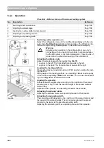
Checklist – Before start-up of the snow clearing system
Switching winter operation on
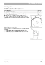
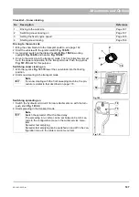
Select the configuration menu in the multifunctional display with the turn-
push knob
and activate winter operation. The Winter service
information symbol
appears in the multifunctional display.
Adjusting the attack angle
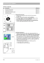
Adjust the attack angle with the joystick
.
•
Joystick to the left: The front attachment swivels to the left
•
Joystick to the right: The front attachment swivels to the right
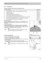
Loading the loading platform
Observe the maximum permissible load of 500 kg when loading the load-
ing platform.
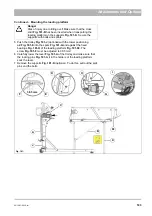
Filling height of the loading platform, see mark
Fig. 185-A
. Load capacity
of the tie-down eyes
Fig. 185-B
: max. 250 daN. You can use the separat-
ing board
for different materials.
Loading the spreader
Different specific weights arise according to the condition of the spread
material (wet or dry). Check the specific weight of the spread material
before filling.
Payload of the spreader, see operating manual of the spreader.
Adjusting the spread volume
Adjusting the spread volume, see operating manual of the spreader.
Adjusting the spreading width
The spreading width depends on the condition of the spread material and
the speed of the spreading disk. The more coarse grained the spread
material is, the larger is the possible spreading width.
Adjusting the spreading width, see operating manual of the spreader.
No.
Description
Reference
1
Switching winter operation on
Page 186
2
Adjusting the attack angle
Page 186
3
Loading the loading platform and spreader
Page 186
4
Adjusting the spreading volume
Page 186
5
Adjusting the spreading width
Page 186
Fig. 184:
A
Warning
Activate winter operation in the configuration menu only in
connection with an uncoded snow blade. In winter operation
the front lift system is not limited downwards. There is a risk of
an accident on unintended lowering of the attachment!
Fig. 185:
C
B
A
Summary of Contents for Citymaster 1600
Page 22: ...22 01 1491 00 12 fm Safety Instructions G A B D E F Fig 3 C F C E C D G A B A...
Page 26: ...26 02 1491 00 11 fm Operation Fig 5 25 23 16 18 17 19 22 21 20 24 26 27...
Page 30: ...30 02 1491 00 11 fm Operation Fig 7 62 63 61 67 55 50 51 54 53 52 58 57 59 60 65 64 66 68 56...
Page 32: ...32 02 1491 00 11 fm Operation Fig 8 75 69 78 73 72 79 80 81 82 83 74 77 70 71 76 84...
Page 85: ...04 1491 00 11 fm 85 Technical Data 4 Technical Data Fig 80 3830 1600 941 1210 975 1964...
Page 146: ...146 06 1491 00 12 fm Attachments and Options 6 1 5 Technical data Fig 144 2215 4510 1580 2250...
Page 220: ...220 06 1491 00 12 fm Attachments and Options...

