background image

Chapter 2 Installation

HD NVR User Manual

2-11

2-2-1 Installation Steps

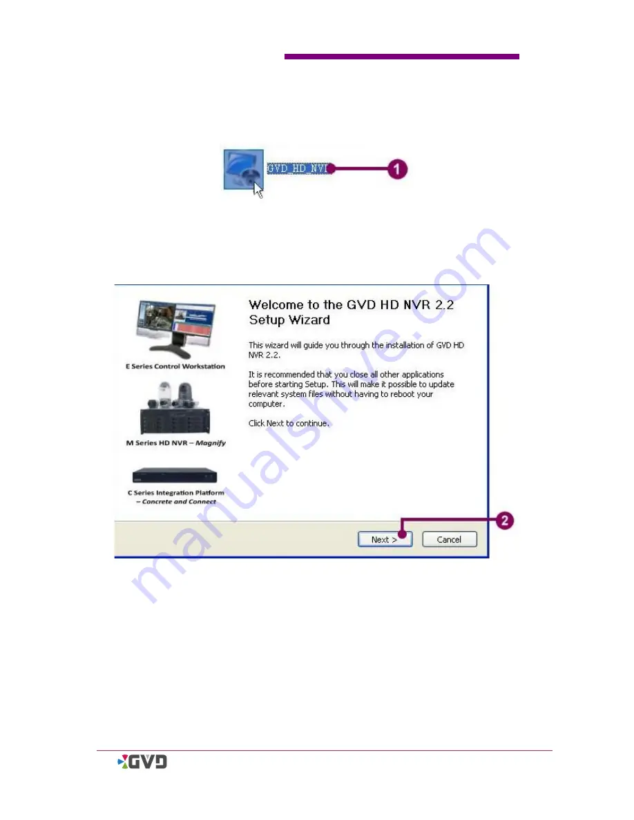
To install the HD NVR Manager, see the following steps:

Figure 2-7 Install the system

1.

In the installation CD, find the setup program of the HD NVR Manager (file name:

GVD_HD_NVR.exe). Double click the setup program.

2.

The setup wizard starts. Click

Next

.

Summary of Contents for M3 series

Page 1: ...Software Authetication 2 19 Chapter 3 SCM Program 3 1 3 1 SCM Brief 3 1 3 2 Run the SCM Program 3 3 3 3 Create a Volume 3 4 3 4 Rename the Volume Name 3 6 3 5 Delete a Volume 3 7 3 6 Modify a Volume 3...

Page 2: ...4 30 4 5 5 Adjust the Image Ratio 4 32 4 5 6 Operate A Map File in the Viewer 4 33 4 5 6 1 Open A Map in the Viewer 4 34 4 5 6 2 Show the Channel Image from the Map 4 35 4 5 6 3 Change the value of th...

Page 3: ...age or the Video File 4 75 4 7 4 Delete the Files in the Spooler 4 77 Chapter 5 Alarm Event Mode 5 1 5 1 Alarm Mode 5 1 5 1 1 Deal with The Alarm 5 2 5 1 2 Turn On Off the Pop up Alarm 5 3 5 1 3 Turn...

Page 4: ...3 1 3 Change the map position in the hierarchy 6 29 6 3 1 4 Delete a map from the system 6 31 6 3 2 User Account 6 32 6 3 2 1 View the setting of the user account 6 32 6 3 2 2 Change the Password of t...

Page 5: ...volume 3 11 Figure 3 8 Detach a hard disk 3 13 Figure 3 9 Save the log 3 14 Figure 3 10 Exit SCM Program 3 15 Figure 4 1 Four basic operation modes 4 1 Figure 4 2 The Display Mode 4 2 Figure 4 3 The...

Page 6: ...52 Figure 4 37 Run the Digital Zoom mode 4 53 Figure 4 38 Snapshot an image 4 54 Figure 4 39 Manual Recording 4 56 Figure 4 40 Open an AVA file 4 57 Figure 4 41 Switch the codec on playing 4 58 Figure...

Page 7: ...nually 6 11 Figure 6 8 Add a channel automatically 6 17 Figure 6 9 Modify the channel settings 6 20 Figure 6 10 Delete a camera channel from the system 6 22 Figure 6 11 The Storage Setting 6 24 Figure...

Page 8: ......

Page 9: ...when the user is manipulating the product The push pin surrounding the green rectangle is intended to remind the user what the specific operation notification is The exclamation point surrounding a re...

Page 10: ...e 2 4GHz or above RAM 2048 MB at least Operation System Windows XP SP2 Windows XP SP3 or above Display nVidia chipset which supports DirectX3D Minimum resolution needs 1280 1024 The recommended resolu...

Page 11: ...the installed application the HD NVR Manager An HD NVR can connect both IP cameras and video server by the network All key operational co mponents are located in the front panel and the rear panel of...

Page 12: ...utput 6 Center Bass Port 7 Rear Surround out port 8 Side Surround out port 9 RJ 45 Gigabit LAN port eth0 10 IEEE 1394 port eSATA Connector 11 S PDIF out port Fiber cable connector 12 USB 2 0 ports 13...

Page 13: ...e the HD NVR Enterprise is able to provide a high quality recording and life viewing function Via the network the HD NVR can connect to both IP cameras and video servers All key operational components...

Page 14: ...PS 2 connection port 3 Keyboard PS 2 connection port 4 S PDIF out port 5 IEEE 1394 ports 6 USB 2 0 ports 7 RJ 45 Gigabit LAN ports port numbers may vary by models 8 Audio Inputs Outputs 9 Exhaust Fan...

Page 15: ...mouse to the USB 2 0 mouse connector 3 Connect the VGA monitor to the VGA port 4 Plug in a CAT 6 UTP cable to the RJ 45 Gigabit LAN port and connect the other end of the cable to a hub or a switch th...

Page 16: ...Chapter 2 Installation 2 6 HD NVR User Manual NOTE The default IP address of the NVR is 192 168 0 10 Contact your network administrator and update the IP address of the NVR...

Page 17: ...r to the DVI VGA ports The number type and position of DVI VGA ports may vary by the models 4 Plug in a CAT 6 UTP cable to the RJ 45 Gigabit LAN port with the green label and connect the other end of...

Page 18: ...e the fixed screws and remove the hard drive Install the hard drive 1 Put the new or repaired hard drive in the HDD tray and lock the fixed screws 2 Insert the HDD tray to the HD NVR Enterprise and pu...

Page 19: ...Chapter 2 Installation HD NVR User Manual 2 9...

Page 20: ...10 HD NVR User Manual 2 2 HD NVR Manager Setup This chapter describes how to install the HD NVR Manager Before using the application the user should complete two procedures 1 Install the HD NVR Manage...

Page 21: ...lation Steps To install the HD NVR Manager see the following steps Figure 2 7 Install the system 1 In the installation CD find the setup program of the HD NVR Manager file name GVD_HD_NVR exe Double c...

Page 22: ...D NVR User Manual 3 A license agreement dialog appears Check I accept the terms in the License Agreement and click Next 4 The setup program lists the minimum hardware requirement Click Next when all h...

Page 23: ...an addition Windows component Message Queuing is required To install Message Queuing refer to Appendix IV for more information NOTE Message Queuing setup program is in the Windows Setup disc Without...

Page 24: ...ect the installed device and click Install The setup program automatically creates a GVD directory in the selected driver 7 The setup program will automatically install Windows Installer 3 1 if the pr...

Page 25: ...5 8 The setup program will automatically install VC80 if the program has not been detected in the operation system 9 The setup program will automatically install NET Framework 2 0 if the application h...

Page 26: ...ion 2 16 HD NVR User Manual 10 The setup program raises a reboot message Click Yes to reboot immediately 11 Click No and the setup program requires the user to reboot manually Otherwise the system may...

Page 27: ...Chapter 2 Installation HD NVR User Manual 2 17 12 Click Finish to complete Restart the Windows...

Page 28: ...cense and activate it There are two kinds of license activation Dongle Key Software Authentication 2 2 2 1 Dongle key The Dongle key is a hardware lock with a USB 2 0 connector After the Dongle key is...

Page 29: ...n 1 Double click the HD NVR icon on the desktop and the GVD License Control dialog appears NOTE Customers who buy the NVR models have passed the software authentication The manufacturer will complete...

Page 30: ...Control dialog The program automatically opens a browser and connects to the registration website Follo w the instructions on the webpage and upload the saved application form 8 The manufacture verifi...

Page 31: ...HD NVR User Manual 2 21 9 Change to the license folder and input the file name and click Open 10 The screen shows the logon dialog Use the manager account and input the default password 6001 Click Lo...

Page 32: ......

Page 33: ...can effectively manage all storage devices installed in the NVR for video recording Before using the HD NVR Manager the administrator should plan all accessible repositories in advance The basic stora...

Page 34: ...Program User Guide 3 2 HD NVR User Manual The SCM uses different icons to show the status of the volumes and hard drivers See the following table for demonstration Volume Hard Driver Normal Disable W...

Page 35: ...ollowing steps Figure 3 2 Run SCM Program 1 In the windows platform click Start All Program Genius Vision Digital HD NVR Storage Configuration Manager 2 When the logon dialog appears select manager in...

Page 36: ...ogram User Guide 3 4 HD NVR User Manual 3 3 Create a Volume To create a volume see the following steps Figure 3 3 Create a volume 1 In SCM program click New Volume 2 Input the new volume name in the V...

Page 37: ...ard disk and lose current data on disk Are you sure to do these jobs Click Yes to continue 7 The system shows a progress bar When the process is complete the device panel has showed the new volume and...

Page 38: ...he name of the volume see the following steps Figure 3 4 Rename the volume name 1 In SCM program click the preferred volume in the device panel 2 Click Rename A Volume rename dialog appears 3 Type the...

Page 39: ...the device panel 2 Click Disable The system shows a confirmation message Are you sure you want to disable this volume Click Yes to continue 3 Click Delete Volume 4 The system shows a confirmation mes...

Page 40: ...Chapter 3 SSMT Program User Guide 3 8 HD NVR User Manual 5 The selected volume has been removed from the volume list...

Page 41: ...sk to an existing volume To add a hard disk to an existing volume see the following steps Figure 3 6 Add a hard disk to an existing volume 1 In SCM program click the preferred volume in the device pan...

Page 42: ...er Guide 3 10 HD NVR User Manual 5 Click OK to continue Or click Cancel to exit 6 Click Enable to restart the volume 7 The system raises a confirmation message Are you sure you want to enable this vol...

Page 43: ...n SCM program click the preferred volume in the device panel 2 Click Disable The system shows a confirmation message Are you sure you want to disable this volume Click Yes to continue 3 Click Modify A...

Page 44: ...apter 3 SSMT Program User Guide 3 12 HD NVR User Manual 6 Click Enable to restart the volume 7 The system raises a confirmation message Are you sure you want to enable this volume Click Yes to complet...

Page 45: ...o detach a hard disk see the following steps Figure 3 8 Detach a hard disk 1 In SCM program click the preferred hard disk in the device panel 2 Click Detach Hard Disk 3 The system raises a confirmatio...

Page 46: ...vents since the program has run SCM program allows the user to save the log to an external file To do so see the following steps Figure 3 9 Save the log 1 Click Log in the main menu 2 Click Save log A...

Page 47: ...al 3 15 3 8 Exit the SCM Program To exit SCM Program see the following steps Figure 3 10 Exit SCM Program 1 Click File in the main menu 2 Click Exit 3 The system raises a message Choose Yes to termina...

Page 48: ......

Page 49: ...al Introduction 4 1 1 Basic Operation Modes The system provides four operation modes The display mode The alarm mode The event mode The configuration mode Click the four buttons at the right hand side...

Page 50: ...D NVR User Manual The display mode allows the user to monitor the images from the channels manipulate the channels or associated DI DO points and export the necessary files See the following demonstra...

Page 51: ...er to preview the recorded video clip of the alarm This mode also provides the user with the alarm searching function that helps the user to find the preferred alarm from numerous alarms Refer to chap...

Page 52: ...system by the user and by the camera The event mode also provides the user with the event searching function that helps the user to find the preferred event from numerous alarms Refer to chapter 5 Ala...

Page 53: ...tion of all connecting devices and allows the user to add modify and delete the connecting devices The storage setting allows the user to review the storage information The system setting includes fou...

Page 54: ...the Display Mode The display mode is composed of the following parts 1 Logo Sys Info 2 Tree Panel 3 Pattern Panel Mode button function button tour list 4 Video Display Panel 5 Spooler Panel See the f...

Page 55: ...des six messages 1 Current Date Time 2 IP address of this machine 3 login account 4 the usage percentage of CPU 5 the usage percentage of memory and 6 the usage percentage of network The alarm in form...

Page 56: ...era 180 degree IP Dome camera and 360 degree IP Dome camera Some specific channels equip with sub channel or digital I O will be shown in the tree By observing the channel icon in the tree the user ma...

Page 57: ...el status See the following table for demonstration Generic D1 Channel High Definition Channel Sub Channel PTZ D1 Channel 180 degree IP Dome 360 degree IP Dome Connected In Recording Video Lost In Rec...

Page 58: ...the DI point and change the value of the DO points To change the value of the DO point see the following steps Figure 4 8 Control the DI DO points 1 Simply double click the selected DO point on the c...

Page 59: ...he can drop it in a viewer to view the image In addition the system allows the user to control the DO points on the map directly just like the way on the camera tree Inherited from its HTML base the m...

Page 60: ...creen From a pattern the user may view different camera images simultaneously By switching different patterns the user may view all camera images in a short time The pattern panel includes two tabs se...

Page 61: ...yout tab click the preferred layout The new layout shows on the video display panel TIP To quickly select the layout the user may press the hot keys of 1 to 9 to switch the preferred layout The 9 hot...

Page 62: ...e icon on the preferred viewer 4 The system automatically plays the selected camera image on the viewer 5 Repeat the steps 3 and 4 until all viewers have shown images NOTE Refer to section 4 5 Viewer...

Page 63: ...associated channels directly There are four function buttons add to the tour list edit name save and delete Figure 4 11 Customize a pattern NOTE When the system restarts the first customized pattern...

Page 64: ...tour list 1 Click the Select layout tab 2 Select the preferred layout template from the select layout list 3 From the tree panel drag the preferred channel or map icons and drop it on the viewers 4 C...

Page 65: ...System Operation HD NVR User Manual 4 17 TIP When the customized patterns in the tour list have more than 12 the user may click the up down button at the right hand side and a vertical pattern list wi...

Page 66: ...ern name see the steps below Figure 4 13 Change the pattern name 1 Click the Tour list tab 2 Click the preferred pattern 3 Click the Edit name button 4 When the Edit name dialog appears type a new pat...

Page 67: ...pattern change When the pattern has been changed see the following steps to save the modification Figure 4 14 Save the pattern change 1 Click the Tour list tab 2 Click the preferred pattern in the to...

Page 68: ...m the tour list To delete a pattern from the tour list the user may see the following steps Figure 4 15 Delete a pattern from the tour list 1 Click the Tour List tab 2 Click the selected pattern 3 Cli...

Page 69: ...dwidth is not enough The followings introduce the speed buttons High Speed All viewers including the active viewer with the white frame plays in full speed Medium Speed Only the active viewer plays in...

Page 70: ...pattern order see the following steps Figure 4 16 Change the pattern order 1 Click the Tour List tab 2 Click the selected customized pattern icon 3 Drag the icon and drop the icon to the preferred po...

Page 71: ...23 4 4 3 Run a Tour The tour function plays all patterns in the tour list by order and by time To run a tour see the following steps Figure 4 17 Run a tour 1 Click the Tour List tab 2 Click the Tour...

Page 72: ...torical image playing image seeking retrieving as well as motion detection A viewer is composed of the channel image the on screen display OSD and four indicators When the user activates the sub chann...

Page 73: ...Camera tree panel 3 Select the preferred channel icon from the camera tree Refer to the section 4 3 1 1 Icon Status for channel icon description 4 Drag the preferred channel icon and drop it in a view...

Page 74: ...rame per second Decode FPS indicate the decode frame per second Render FPS indicate the render frame per second Timestamp indicate the timestamp of the playing image Latency indicate the latency of th...

Page 75: ...d in the lower left corner of the viewer The Time stamp shows the date and time of the playing image The option allows the user to change the display color and the time format Time Line the time line...

Page 76: ...eckboxes in the dialog The example panel at the lower part of the dialog shows the preview 3 When the color of the channel name or the time stamp i s close to the background the user can click the col...

Page 77: ...p and the viewer shows the new time format of the timestamp 6 When the K 200 keyboard has been connected an option of Monitor Viewer Camera appears If the option is checked a specific code number of K...

Page 78: ...attern When the playing image comes from the mega pixel camera the function helps the user to review more details in the image To maximize the viewer see the following steps Figure 4 21 Maximize the V...

Page 79: ...teps 2 and 3 Double click the stretched viewer and the system will recall the original pattern TIP If necessary the user may click the Full Screen button to show the viewer in the full screen mode TIP...

Page 80: ...er set the viewer active 2 Right click the mouse and a pop up menu appears 3 Move the mouse to the Display item and a sub menu appears 4 The sub menu includes two options Image Aspect Ratio and Full V...

Page 81: ...the Viewer The viewer can open not only the general channel image but also the HTML based map file A map file allows the user to conduct the following three operations 1 Open a map in the viewer 2 Sho...

Page 82: ...con and drop it to a viewer 3 The map shows in the viewer TIP The map is a HTML based file Simply click the hyperlink in the map and the viewer can be run as a browser TIP The system allows the map vi...

Page 83: ...image from the map directly follow the steps Figure 4 24 Show the channel image from the map 1 Click the selected camera icon in the map 2 Drag the icon and drop it in other viewer 3 The viewer plays...

Page 84: ...to change the value of the DO point directly To change the value see the steps below Figure 4 25 Change the value of the DO point from the map 1 Double click the DO icon in the map A DO Control dialog...

Page 85: ...play the image of the sub channel see the following steps Figure 4 26 Play the image from a sub channel 1 Click the Display Mode button 2 Click the Device tab in the Camera tree panel 3 Show the sub c...

Page 86: ...n horizontal vertical or diagonal direction The camera can also change the len s focus for a wider or closer image There are three key features that the PTZ camera has Panning control the camera lens...

Page 87: ...viewer see the following steps Figure 4 27 The Panning and tilting function of the PTZ camera 1 Refer to section 4 6 Time Slider to show the Time Slider and click the PTZ mode TIP Press the hot key O...

Page 88: ...4 System Operation 4 40 HD NVR User Manual 3 The viewer shows the moving image as the lens of the PTZ cam era moves When the viewer has shown the preferred image the user releases the left key of the...

Page 89: ...on of the PTZ camera see the following ste ps Figure 4 28 The zoom in out function of the PTZ camera 1 Refer to section 4 6 Time Slider to show the Time Slider and click the icon of the PTZ mode 2 If...

Page 90: ...Move to preset 1 Refer to section 4 6 Time Slider to show the Time Slider and click the icon of the PTZ mode 2 Right click the mouse in the viewer and a pop up menu appears 3 Move the cursor to the T...

Page 91: ...how the Time Slider and click the icon of the PTZ mode 2 Run the panning tilting and zooming functions of the PTZ camera until the preferred image appears on the viewer 3 Right click the mouse and a p...

Page 92: ...c scene must become the center focus To run the function see the following steps Figure 4 31 Move to Center 1 Refer to section 4 6 Time Slider to show the Time Slider and click the icon of the PTZ mod...

Page 93: ...Chapter 4 System Operation HD NVR User Manual 4 45 5 The PTZ camera has moved to the new center...

Page 94: ...o Home To move the lens of the camera to the Home point see the following steps Figure 4 32 Move to the Home point 1 Refer to section 4 6 Time Slider to show the Time Slider and click the icon of the...

Page 95: ...s Figure 4 33 Save the Home point 1 Refer to section 4 6 Time Slider to show the Time Slider and click the PTZ mode 2 Move the lens to the scene of the new Home point 3 Right click the mouse in the vi...

Page 96: ...ion of the mega pixel camera makes the ROI image more distinctly even though the image has been partially enlarged When the ROI is created a yellow rectangle frame appears on the image area representi...

Page 97: ...and a sub menu appears 3 Click Create a ROI 4 A yellow rectangle frame appears on the viewer Move the mouse to the bottom left corner of the frame and hold the left key Drag the corner until the size...

Page 98: ...anual TIP In the target viewer hold the Shift key first and hold the left key of the mouse to drag a rectangle area a new ROI will be created directly NOTE When the ROI has moved in the original viewe...

Page 99: ...4 5 9 2 Hide a ROI To hide a ROI see the following steps Figure 4 35 Hide a ROI 1 Right click the mouse in the original ROI viewer and a pop up menu appears 2 Move the mouse to the ROI item and a sub...

Page 100: ...ing steps Figure 4 36 Delete a ROI 1 Right click the mouse in the original ROI viewer and a pop up menu appears 2 Move the mouse to the ROI item and a sub menu appears 3 Click Delete ROI 4 The ROI has...

Page 101: ...ick the Digital Zoom Mode 2 Click the selected viewer and set the viewer active 3 To zoom in the image roll down the wheel of the mouse and the image will be enlarged To zoom out the image roll up the...

Page 102: ...or printed out fo r user s need To snap shot an image see the following steps Figure 4 38 Snapshot an image 1 If the selected viewer is not the active viewer set the viewer active 2 Right click the mo...

Page 103: ...Chapter 4 System Operation HD NVR User Manual 4 55 TIP To quickly capture the image the user can simply press F11 or the hot key E In addition the user may click the snapshot button in the time slider...

Page 104: ...menu and a sub menu beside the menu appears 4 In the sub menu there are four items 30 seconds 10 minutes 30 minutes and more Click the preferred item to run the function TIP Press the F10 or the hot k...

Page 105: ...open an ava file see the following steps Figure 4 40 Open an AVA file 1 Right click the mouse in the selected viewer and a pop up menu appears 2 Click Open AVA File 3 A file open dialog appears Browse...

Page 106: ...the dual codec camera and a pop up menu appears 2 Move the cursor to the Switch Codec item and a sub menu appears 3 Depending on the supporting feature of the camera there are three to f our options i...

Page 107: ...ct the Image To disconnect the image see the following steps Figure 4 42 Disconnect the image 1 Click the selected viewer and set it active 2 Right click the mouse and a pop up menu appears 3 Click Di...

Page 108: ...e Slider offers the playback function and the user may play the historical video forward and backward The speed control function of the Time Slider controls the playing speed of the active viewer If n...

Page 109: ...estamp the video timestamp 3 Actions The playing status of the viewer including the following items Live The viewer is playing a live video nx the backward playing speed of the video the valu e of n i...

Page 110: ...s 15m 15 minutes 30m 30 minutes 1hr 1 hour 12hr 12 hours and 1d 1 day Nail Bar Timeline The nail bar is at the top of the Time Slider The nail bar shows the time interval of the playing image There ar...

Page 111: ...ing and the jump buttons for rapidly moving the playing index The followings describe the functions of buttons Operation buttons a Reverse the video b Pause the video c Play the video d Move to the pr...

Page 112: ...ws the user to change the playing speed when playing a historical video Mode buttons for changing three operation modes Normal mode PTZ mode and Digital Zoom mode in the viewer Export buttons these tw...

Page 113: ...n Figure 4 44 Search the video by the period button 1 Click the 12h button 2 Move the playing index to the beginning of the timeline 3 Click the 5m button 4 Move the playing index to the right and sto...

Page 114: ...The viewer plays the historical video immediately By the jump button Figure 4 47 Search the video by the jump button 1 Keep clicking the jump button 5m at the left hand side until the target coordinat...

Page 115: ...nd find the target playing index in the timeline 4 Double click the time index and the viewer starts playing the historical video 5 To playback the video simply click the reverse play button 6 To chan...

Page 116: ...ollowing steps Figure 4 49 Export to the spooler 1 Refer to the last section and play a historical video 2 Click the Export to spooler button Or right click the mouse in the nail bar and select Export...

Page 117: ...upper timeline Click Display Option from the pop up menu to open the color panel of the timeline 2 The color panel provides 6 options alarm index recording motion activity alarm recording manual recor...

Page 118: ...Chapter 4 System Operation 4 70 HD NVR User Manual 6 Close the color panel and the color of the modified sy mbol has been changed...

Page 119: ...ike the combination of an independent viewer and a time slider The following figure shows the composed elements of the GVD player Figure 4 51 Brief of the GVD Player a The menu b The viewer c The info...

Page 120: ...ava file in the GVD player 1 In the Windows platform click Start All Programs Genius Vision Digital HD NVR GVD Player to run the GVD player 2 Click the Open AVA file menu item when the GVD player appe...

Page 121: ...ows the user to preview captured pictures and video clips before they are exported to other storage media 4 7 1 View the Image To view the exported picture in the spooler see the following steps Figur...

Page 122: ...spooler see the following steps Figure 4 54 View the video clip in the spooler 1 Click the selected item with a film icon in the spooler 2 Double click the preview picture of the selected item 3 The G...

Page 123: ...e To save the selected item to other storage device like flash disk see the following steps 1 Check the checkbox of the selected items TIP Check the Select All checkbox all items in the spooler will b...

Page 124: ...4 When any ava file is selected the user can check the checkbox of the Embed Quick Player The option will include the GVD player after file exporting 5 Click Start The Items table shows the relative i...

Page 125: ...55 Delete the files in the spooler 1 Check the checkboxes of the selected items TIP Check the Select All checkbox all items in the spooler will be selected 2 Click the Delete button at the bottom of...

Page 126: ......

Page 127: ...ode includes three parts The searching condition panel is located at the upper left corner of the screen The panel provides the user with the alarm searching function The spooler is located at the low...

Page 128: ...rm has not been neither reviewed nor taken any actions When the alarm has been reviewed by the user but no action for example put some comments has been taken or the cause of the alarm has been automa...

Page 129: ...n on off the pop up alarm The pop up alarm icon located in the system tab is a toggle button to turn on off the pop up alarm To turn off the pop up alarm simply click the icon and the pop up alarm wil...

Page 130: ...on off the alarm sound The alarm sound icon is located in the system tab and is a toggle button to turn on off the alarm sound To turn off the alarm sound simply click the icon and the alarm sound wi...

Page 131: ...ected options and set the values of the searching conditions The options include Status Search by the alarm status Priority Search by the alarm priority Trigger Time Search by the generated date time...

Page 132: ...an alarm 1 Double click the active or pending alarm in the alarm list 2 An Alarm Details dialog appears Put some comments in the Comment column NOTE If the Comment column is blank the alarm cannot be...

Page 133: ...edge several alarms together 1 Check the checkboxes of the selected alarms in the alarm list To select all alarms check the All checkbox 2 Click Complete 3 A Complete Multiple Alarms dialog appears Pu...

Page 134: ...rch tab in the Alarm list Click the desired alarm from the searching list 2 Click the Export button at the right hand side of the Time slider The picture or video clip will be exported to the spooler...

Page 135: ...e listed in the Events table The table includes five columns Figure 5 7 Details of the Events table a Category indicate the event category including System User Camera Events b Event Time indicate the...

Page 136: ...user to search the events by the triggered time See the following steps Figure 5 8 Event Search By Time 1 Click the Event Mode icon 2 Click the drop down box and select the HD NVR name in the Search...

Page 137: ...gure 5 9 Event Search By Category 1 Click the Event Mode icon 2 Click the drop sown box and elect the HD NVR name in the Search by HD NVR field 3 Check the checkbox of the Search by Category option 4...

Page 138: ...xport the events see the following steps Figure 5 10 Export the events 1 Click the Export button at the bottom of the Events table A Save As dialog appears 2 Input the new file name in the File name c...

Page 139: ...s of the configuration mode 1 Information Panel see chapter 4 2 Mode buttons See chapter 4 3 Category panel 4 Setting panel 5 Spooler See section 4 7 Spooler When entering the configuration mode there...

Page 140: ...y the values of specific items The NVR Setting is composed of three tabs 1 The basic setting 2 The customized setting 3 The License Control TIP To change the setting values in the device tab click the...

Page 141: ...ll check the connection status every 2500ms If the network packet has lost for more than 2000 ms and the system raises the video loss alarm In level 1 the system will check the connection status every...

Page 142: ...ng Decide whether the NVR setting is synchronized with the saved setting in the remote devices When the checkboxes is checked the NVR will send the reserved setting to the remote devices and overwrite...

Page 143: ...on 3 License term includes the starting and ending date and time of the Use Term and the Patch Term 4 Constraint indicates the maximum number of the connecting channels and the repositories 5 Support...

Page 144: ...HD NVR User Manual 6 1 1 3 Customized Setting The customized setting includes three parts Figure 6 4 Customized Setting of the NVR 1 Display setting 2 File Format setting 3 Alarm Rule setting 4 Langua...

Page 145: ...format of snapshot image JPG BMP Select one of the following options as the default file format of export clip AVA AVI Alarm setting The alarm setting includes the following option Enable Sound indica...

Page 146: ...the code name recorded in the keyboard controller program of the K 200 PTZ keyboard If unchecked the code name is hidden Others When the option is unchecked the system raises a warning dialog automati...

Page 147: ...l settings vary depending on the camera models For example when an Arecont s camera is selected the information includes the following 6 tabs Figure 6 5 The channel information in the setting panel a...

Page 148: ...ser Manual Figure 6 6 The camera setting provided by the manufacturer Some tabs will show the live image of the channel An IP address is above the live image Click the IP address and a browser will be...

Page 149: ...he system offers two ways manual or automatic Add a Channel Manually To add a channel manually see the following steps Illustrated by the Arecont 3130 model Figure 6 7 Add a channel manually 1 In the...

Page 150: ...nection is successful and the camera information including an image preview will be shown in the list below 6 Click Import Camera to add the channel Click Back to return the Add Camera Device dialog o...

Page 151: ...plies the default values 8 The new channel has been added to the camera tree A Configuration page is opened for the following camera settings 9 Click the Video tab and change the channel name If neces...

Page 152: ...g mpeg4 from the drop down list 2 Click the Recording Format combo box Select Jpeg or MPEG4 from the drop down list If the recording format of the channel is MPEG4 and the codec mode of the viewer is...

Page 153: ...lick the Storage tab and click the Assign Storage button NOTE If the volume has not been created the Assign Storage button is unable to work Close the configuration page and create a new volume first...

Page 154: ...can also change the Mode option to control the DI DO points if necessary 14 Click OK to complete TIP How to set the motion alarm area illustrated by Arecont s 3130 model 1 In the configuration page cl...

Page 155: ...hannel automatically see the following steps Figure 6 8 Add a channel automatically 1 In the configuration mode click the Device tab 2 In the category panel click the Add button to show the Add Camera...

Page 156: ...tomatically searches all vendor s connecting IP cameras in the network The searching result will be listed in the channel table 7 Check the checkboxes of the selected cameras and click Install 8 The n...

Page 157: ...Chapter 6 Configuration Mode HD NVR User Manual 6 19 TIP Right click the channel node to show the pop up menu There are three items add camera modify camera and delete camera See the following figure...

Page 158: ...a channel follows the steps below Figure 6 9 Modify the channel settings 1 In the configuration mode click the Device tab 2 Click the preferred channel from the camera tree 3 Click the Modify button t...

Page 159: ...lues Refer to section 6 1 2 2 Add a camera channel to the system for the all channel settings 5 If necessary click the Video page to change the setting value of the sub channel 6 If the camera has DI...

Page 160: ...click the sub channel or DI DO point NOTE To delete a sub channel refer to section 6 1 3 3 Modify the camera channel settings and open the configuration page Uncheck the Enable Sub Channel checkbox i...

Page 161: ...been assigned to the image recording or the channel is used in an alarm rule the system raises a message Click OK to continue Or click Cancel to exit 5 The selected channel has been removed from the c...

Page 162: ...he volume will be shown in the setting panel Figure 6 11 The Storage Setting The setting panel shows the following information 1 Volume name indicate the name of the volume 2 HD shows the repository i...

Page 163: ...tting The system setting includes four items Map User Account Alarm Rule Schedule 6 3 1 Map In the configuration mode the system offers the following functions Add a map to the system Modify a map Del...

Page 164: ...system 1 In the configuration mode click the System tab 2 Click HTML Maps in the category panel 3 Click Add button to show the Add Map dialog 4 Input a new name in the Map Name column 5 Input the URL...

Page 165: ...iguration only the XML based and HTML based files are supported NOTE Refer to Appendix III How to add camera or DI DO to a HTML map for adding a camera or DI DO icon to the HTML map TIP Right click th...

Page 166: ...ick HTML Maps in the category panel 3 Click the selected map 4 Click Modify button to show the configuration page 5 The configuration page has two tabs the HTML tab shows the content of the map file a...

Page 167: ...o change the hierarchical structure of the map see the following steps Figure 6 14 Change the map position in the hierarchy 1 In the configuration mode click the System tab 2 Click HTML Maps in the ca...

Page 168: ...ed map in the map hierarchy Click the buttons at the bottom to adjust new position The functions of the buttons are as follows Upgrade the map level Downgrade the map level Move the map up Move the ma...

Page 169: ...To delete a map from the system see the followi ng steps Figure 6 15 Delete a map from the system 1 In the configuration mode click the System tab 2 Click HTML Maps in the category panel 3 Click the...

Page 170: ...the user account In the configuration mode click the user account and the setting panel shows the following information Figure 6 16 View the setting of the user account Name indicate the name of the u...

Page 171: ...e the following steps Figure 6 17 Change the password of the user account 1 Click the System tab in the category panel 2 Click the manager icon in the category panel 3 Click the Modify button to show...

Page 172: ...r 6 Configuration Mode 6 34 HD NVR User Manual TIP Right click the user account node to show a pop up menu Click Change Password to change the password of the user account directly See the following f...

Page 173: ...ry of the alarm rule will be shown in the setting panel The content of an alarm rule includes Figure 6 18 Brief of the alarm rule 1 Basic setting indicate the basic information of the alarm rule inclu...

Page 174: ...3 2 Add an alarm rule to the system To add a new alarm rule see the following steps Figure 6 19 Add an alarm rule to the system 1 In the configuration mode click the System tab 2 Click Rule in the cat...

Page 175: ...e priority and the schedule The name and the priority of the alarm rule are used in the alarm searching conditions Click Next when all settings in the step have been completed TIP If a new schedule ha...

Page 176: ...l 5 The second step is to select the alarm triggering condition There are three categories system user and channel event Check the checkboxes of all preferred conditions and the summary table below li...

Page 177: ...ion To enable the alarm rule check the Set alarm option The channel action decides which channel will be active when the alarm rule is triggered To set the channel action click the preferred channel a...

Page 178: ...tern layout list Click the desired speed button to decide the playing speed of the alarm image 3 Drag the preferred channel and drop it in a viewer Click the Map tab to set the preferred map in the sp...

Page 179: ...popup in the alarm rule 1 At the third step check the Dialog Popup option 2 Input the text of the dialog title 3 Set the severity of the dialog 4 Input the message of the dialog 7 The Alarm Rule Wiza...

Page 180: ...tion Mode 6 42 HD NVR User Manual TIP Right click the alarm rule node to show the pop up menu From the pop up menu the user can directly add a new rule modify an existing rule and delete a rule See th...

Page 181: ...3 3 3 Modify an alarm rule To modify an alarm rule follows the steps Figure 6 20 Modify an alarm rule 1 In the configuration mode click the System tab 2 From the alarm rule list click the preferred a...

Page 182: ...Chapter 6 Configuration Mode 6 44 HD NVR User Manual 4 Follow the steps 4 7 in section 6 3 3 2 Add an alarm rule to the system to modify the rule...

Page 183: ...elete an alarm rule from the system see the following steps Figure 6 21 Delete an alarm rule from the system 1 In the configuration mode click the System tab 2 From the alarm rule list click the prefe...

Page 184: ...ation Figure 6 22 Brief of the Schedule Configuration The schedule setting will help the user to setup the schedules of actions such as recording or alarm triggering The schedule configuration include...

Page 185: ...3 4 2 Add a new schedule to the system To add a new schedule to the system see the following steps Figure 6 23 Add a new schedule to the system 1 In the configuration mode click the System tab 2 Clic...

Page 186: ...n is selected set the start time and the end time 6 If the Weekly option is selected click the cells in the time table The selected cell will become grey 7 Click OK to continue 8 The new schedule has...

Page 187: ...4 3 Modify a schedule To modify a customized schedule see the following steps Figure 6 24 Modify a schedule 1 In the configuration mode click the System tab 2 Click the preferred schedule in the sche...

Page 188: ...Chapter 6 Configuration Mode 6 50 HD NVR User Manual 4 Select the desired option and change the setting values 5 Click OK to close the configuration page...

Page 189: ...le see the following steps Figure 6 25 Delete a customized schedule from the system 1 In the configuration mode click the System tab 2 Click the preferred schedule in the schedule list 3 Click Delete...

Page 190: ......

Page 191: ...D Move to next frame N A Yes P Change Pattern Speed N A N A shift Create ROI N A N A control Drag n drop ROI N A N A O PTZ N A N A Z Digital Zoom N A N A ESC Close full screen Close alarm popup N A 1...

Page 192: ...erval Max packet lost interval l e v e l 1 w o r s t 7 0 0 0 m s 6 0 0 0 m s l e v e l 2 5 0 0 0 m s 4 0 0 0 m s l e v e l 3 5 0 0 0 m s 4 0 0 0 m s l e v e l 4 m e d i u m 3 5 0 0 m s 3 0 0 0 m s l e...

Page 193: ...ng src vl icon PTZ_VL png src a icon PTZ_Alarm png src ar icon PTZ_Alarm png style position absolute top 685px left 1128px width 32px height 32px Add an DI point img type channel di nvr ip 192 168 1 1...

Page 194: ...ctive icon Alarm ON png src do active alarm icon Alarm ON_alarm png src do inactive alarm icon Alarm OFF_alarm png src do inactive icon Alarm OFF png style position absolute top 42px left 1021px width...

Page 195: ...ows desktop click Start Control Panel Add or Remove programs 2 An Add or Remove Programs dialog shows Before continuing load the Windows Setup disc 3 Click Add Remove Windows Components 4 When the Win...

Page 196: ...Appendix f HD NVR User Manual 5 In the subcomponents list check the MSMQ HTTP Support item 6 Click OK to continue 7 In the Windows Component Wizard Click Next to continue...

Page 197: ...e source directory Make sure the source directory is correct If the source directory is uncertain click Browse to select the setup directory 9 Click OK to continue 10 When the installation is complete...

Reviews: