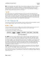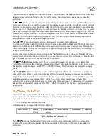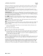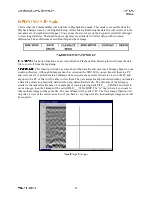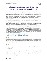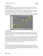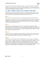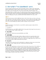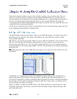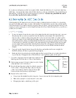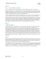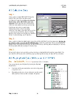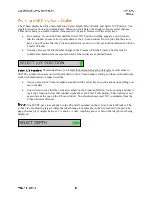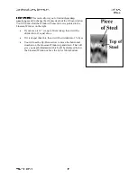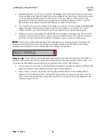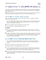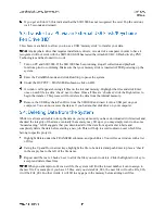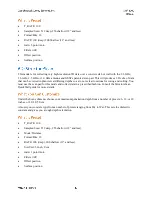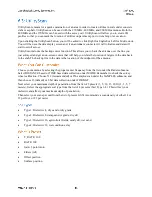
Pictured at the right is the full Collect Menu tree from the Quick3D
mode. The blue boxes enclose the menu choices which are new to
the Quick3D. The following sections explain what they are and
present a step by step guide to set up the software.
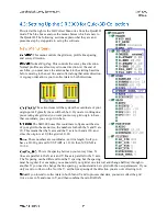
This menu controls the grid size, profile line spacing,
and survey direction.
Normal/Zig-Zag. This controls the survey line direction.
Normal profiles are all surveyed in one direction. At the end of
each line, you must move the antenna back to the starting baseline
before moving to the next line and collect along that same direction.
A zig-zag order allows you to collect data in both directions.
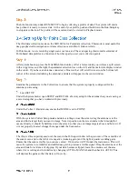
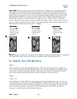
These two items tell the system the coordinate of your
origin point. Typically these will both be 0. If you are working on a
pre-existing site grid and you want your survey grid origin to have
that coordinate, you can put it in here.
The SIR 3000 uses this coordinate to figure out the size
of your grid. In the menu tree, the numbers for both the X and Y are
20. This means that the X axis and the Y axis both end at 20, and
since the origin is at 0,0 the grid is 20×20.
These numbers are coordinates, not line length. So if you
have a 20×20 grid and X/Y START is 10×10, then X/Y END is
30×30.
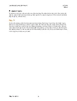
This is the spacing between your survey lines. X
lines are parallel to the X axis and Y lines are parallel to the Y axis.
The X spacing can be different from the Y spacing, but the spacing
must be regular. For example, you cannot start your grid at one interval and change halfway through to
another. If you need to change the line spacing, you must start a new grid with the new parameters. If you
only want to collect on the X or the Y, set the line spacing of the direction you are not collecting to 0.
If you intend to collect data in both X and Y and to process that data, you must collect the grid
twice: once in X and once in Y, and then combine them in RADAN.

