This menu controls the position of Time-Zero. Time-Zero is the location of the beginning of the time
range, and thus the beginning of the scan. Typically, having the system auto locate itself is enough to
adequately set the position. If however, you need to manually adjust the location of Time-Zero, this is the
place to do it. Position contains three additional menus: MANUAL/AUTO, OFFSET, and SURFACE.
The MANUAL/AUTO toggle will allow you to make adjustments in manual mode
and cause the system to re-servo (just like in the gain menu) when switched back to auto. GSSI
recommends that inexperienced users keep the position set to Auto. This choice is automatically set to
MANUAL if you are using sample densities of 4098 or 8192.
This is an internal system parameter that describes the time lag (in ns) from the SIR 3000
triggering the pulse inside of the control unit until we consider it to have transmitted from the antenna
itself. Since there is no way to accurately measure the exact moment the pulse leaves the antenna, we use
the antenna’s direct coupling to figure out the appropriate point to set the offset (and thus the transmit
pulse). The direct coupling is the pulse that travels inside of the antenna housing, directly from the
transmitter to the receiver, and it is generally considered to be the first response in the data.
As long as the antenna dipoles are not very far apart, as is the case with a separated bistatic antenna pair,
the direct coupling happens before any reflections from the ground. So if we make sure that we have the
direct coupling visible in the data, we can be sure that we have 100% of our data and most importantly,
the ground surface to perform a depth calculation. The number here is nanoseconds from trigger pulse
inside the SIR 3000. If you need to adjust this parameter, use caution not to lose that direct coupling
wave.
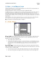
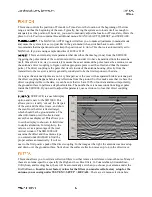
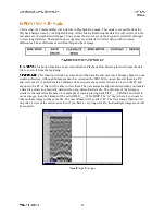
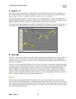
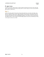
SURFACE, is a useful display
option and is new to the SIR 3000. This
allows you to visually ‘cut out’ the flat part
of the scan and the direct wave, and show
the scan from the first reflected target,
which should be the ground surface. The
other information is still collected and
saved, but not displayed. This allows you
to set the display to show an in-field time
to depth calculation. For simplicity, the
value is set as a percentage of the total
vertical window. The SIR 3000 will
examine the offset and the antenna type
you entered under RADAR to find the
proper surface automatically. It will set
near to the first positive peak of the direct coupling. In the image at the right, the antenna was moved up
and down over the ground surface. Notice how the surface reflection moves up to join the direct wave.
This menu allows you to set data collection filters to either remove interference or smooth noise. Many of
these are antenna-specific, especially the High and Low Pass filters. In ConcreteScan, StructureScan,
UtilityScan, and GeologyScan, these will be automatically set when you choose your antenna under the
RADAR menu.
In order to set factory values for the filters you must recall a factory setup for the
antenna you are using under SYSTEM > SETUP > RECALL
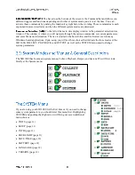
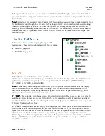
. There are six menu selections here:

