


-58-
Model G0853 (Mfd. Since 07/18)
Aligning Scoring Blade
1. DISCONNECT MACHINE FROM POWER!
2. Adjust main blade tilt to 0° and raise blade all
the way up.
3. Raise blade guard up and move it away from
blade.
4. Align scoring blade body horizontally to main
blade body by:
a. Rotating knurled lock collar shown in
Figure 106 counterclockwise to loosen it.
c. Rotating alignment adjustment knob to
align bodies of blades.
Note:
Rotating knob clockwise moves
scoring blade to the left and counter-
clockwise moves it to the right.
d. Tightening lock collar clockwise to secure
setting.
5. Align scoring blade kerf to main blade kerf by:
a. Positioning straightedge on one side of
main blade flat on table and against main
blade and scoring blade teeth.
b. Rotating knurled lock collar behind eleva-
tion adjustment knob (see
Figure 106)
counterclockwise to loosen it.
c. Using elevation adjustment knob to adjust
scoring blade so that the edge of scoring
blade teeth are aligned with main blade
teeth.
Note: Rotating knob clockwise lowers
scoring blade and counterclockwise
raises it.
d. Tightening lock collar clockwise to secure
setting.
6. Repeat Step 5 for other side of blades to
verify kerf thickness matches and scoring
blade is aligned with main blade.
7. Close blade cover, properly reposition blade
guard, and slide table back to center of
machine.
8. Perform a test cut and check for chip-out.
— If there is chip-out, repeat this procedure
until corrected.
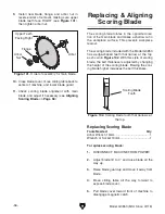
Figure 106. Scoring blade adjustment controls.
Alignment
Adjustment Knob
Elevation
Adjustment Knob
Lock
Collar
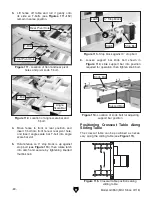
Figure 107. Example of straightedge placed flat
against main and scoring blades.
b. Positioning straightedge against flat of
main blade body (not teeth) and extend-
ing it over scoring blade body (see
Figure 107).
Summary of Contents for G0853
Page 24: ...22 Model G0853 Mfd Since 07 18 5mm Hardware Recognition Chart...
Page 140: ......


