


-42-
Model G0853 (Mfd. Since 07/18)
Before the machine can be connected to the
power source, an electrical circuit and connec-
tion device must be prepared per the
POWER
SUPPLY section in this manual; and all previous
setup instructions in this manual must be com-
plete to ensure that the machine has been assem-
bled and installed properly. The disconnect switch
installed by the electrician (as recommended) is
the primary means for disconnecting or connect-
ing the machine to the power source.
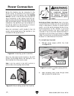
Power Connection
Figure 68. Connecting power to machine.
Move the disconnect switch handle to the ON
position, as illustrated below. The machine is now
connected to the power source.
Figure 69. Disconnecting power from machine.
Move the disconnect switch handle to the OFF
position, as illustrated below. The machine is now
disconnected from the power source.
Note: Lock the switch in the OFF position to
restrict others from starting the machine.
Electrocution, fire, shock,
or equipment damage
may occur if machine is
not properly grounded
and connected to power
supply.
Note About Phase Converters: Due to the start-
up load from this machine, we do not recommend
using a static phase converter to create 3-phase
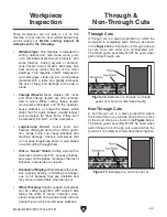
power—as it can quickly decrease the life of elec-
trical components on this machine. If you must
use a phase converter, only use a rotary phase
converter. Only connect the manufactured leg or
"wild wire" to the S terminal (see location on
Page
106). The S terminal can handle power fluctuation
because it is wired directly to the motor.
To connect saw to power:
1. Remove power supply junction box cover
(see
Figure 70).
2. Insert incoming power wires through strain
relief at bottom of junction box.
Figure 70. Location of power supply junction
box.
Strain Relief
Power Supply
Junction Box
Summary of Contents for G0853
Page 24: ...22 Model G0853 Mfd Since 07 18 5mm Hardware Recognition Chart...
Page 140: ......


