X. Pilot Circuit
22
Form No. 29704
Pilot fluid flow/pressure serves joystick operation, boom tilt, steering & travel functions and auxiliary hydraulic
functions (optional). Pilot fluid is supplied from a 6.6 GPM pilot pump. The rear section of the tandem gear pump, at
pilot pump, is driven at engine speed by the thru-drive of the swing pump.
Fluid from the pilot pump flows through an inline pilot filter in the engine compartment. The pilot filter includes a 10-
micron element and a pop-up filter condition indicator. From the filter, fluid flows to the pilot manifold. Always check
the bypass indicator after hydraulic fluid is warmed to at least 120° F. Cold fluid will increase bypass indication.
In the pilot manifold, a relief valve limits pilot system pressure to 480 PSI. Excess fluid from the pilot system returns to
the reservoir through the relief valve. This excess (dump) fluid goes through the heat exchanger (oil cooler) and
return filter.
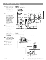
See Figure 20, Figure 20A and Figure 20B
Pilot fluid from the manifold supplies the swing pilot
charge pressure valve, (pressure reducing valve), and pilot solenoid valve in the valve compartment (which has a
solenoid valve to turn the controls on/off). The pilot solenoid valve is controlled by a switch that is triggered using
the right-hand armrest controls. The pilot solenoid valve supplies pilot fluid to the joystick controls, foot pedal
controls and swing brake release valve.
Two joysticks and two foot pedals control machine functions.
See Figure 23 and Figure 24
The boom/hoist control
curves are different than the swing/tool curves. All functions except tilt are controlled by hydraulic pilot signals.
Piloted end caps on each control valve receive the pilot signal. Both the valve control curve and spool centering are
determined by springs in the end caps.
See Figure 43
Tilt is controlled by a rocker switch, speed switch and electrical end caps on the control valve. Electrical proportional
solenoids on the valve meter pilot fluid to the tilt valve end caps. If an auxiliary valve is provided, it is actuated
similar to the tilt valve. However, the solenoids on the auxiliary valve are simple on/off-type solenoids. Auxiliary
circuit speed control comes from spool stroke limit adjusters for the auxiliary valve.
FIGURE 19
PILOT PUMP SUPPLY
P
T
A/B
RP
-
-
-
-
Pilot Pressure
Tank
Main Control Valve Ports
Reduced Pilot Pressure
Main Control
Valve Blank
Propel
Propel
Boom
Tool
Hoist
Tilt
Auxilary
Diverter
Main Control
Valve Blank
R.H.
Joystick
Boom
Swing Tilt
L.H.
Auxilary
Hoist
Tool
Left
Track
Propel
Swing
Brake
Release
Valve
Pilot Pressure
Crawler
Hi/Low
-Speed
Pilot
Manifold
480 PSI
Pilot
Cut Off
Valve
Pressure
Reducing
Valve
350 PSI
Swing
Charge
Valve
Located In
Swing Pump
Pilot Pump
Filter
Right
Track
Propel
A
B
A
B
T
P
P
T
Tilt & Auxilory End Caps Energized Electronically
NOTE!
NOTE!
NOTE!
NOTE!
NOTE!
Hydraulic Fluid Path Simplified For Clarity
NOTE!
NOTE!
NOTE!
NOTE!
NOTE!
Summary of Contents for XL4000
Page 2: ......
Page 73: ......
Page 76: ... 5MP ...
Page 145: ......
Page 146: ......
Page 160: ......
Page 161: ......
Page 162: ......
Page 175: ......
Page 176: ......
Page 177: ......
Page 178: ......
Page 192: ......
Page 193: ......
Page 194: ......
Page 207: ......
Page 208: ......
Page 210: ...500P ...
Page 229: ......
Page 230: ......
Page 245: ......
Page 246: ......
Page 247: ......
Page 248: ......
Page 265: ......
Page 266: ......
Page 267: ......
Page 268: ......
Page 280: ......
Page 281: ......
Page 282: ......
Page 297: ......
Page 298: ......
Page 299: ......
Page 300: ......
Page 301: ......
Page 302: ......
Page 303: ......
Page 304: ......


