Form No. 29703
XL 4100/XL 5100 HYDRAULIC SYSTEM OPERATIONS MANUAL
The swing pump is driven by the PTO drive of the main pump and turns at the some RPM as the engine. It has a
rotary piston group and gear-type charge pump.
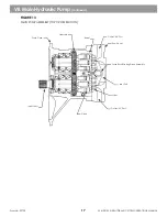
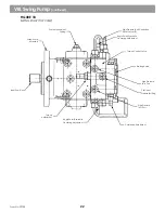
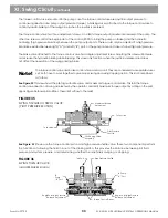
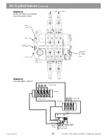
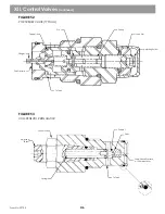
See Figures 15 & 16
Mechanical power from the engine is
changed to hydraulic power at the pump, then changed back to mechanical power whenever the swing motor
drives the pinion of the swing transmission. Swashplate angle in the pump determines the direction and rate of
fluid flow from the pump into the motor. The stroking piston in the pump case shifts the swashplate via a guide
pin. Springs are used to return the stroking piston to center. A stroke limiter sleeve controls maximum swashplate
angle. A tie rod assembly provides a guide for the stroking piston and is used to mechanically center the pump.
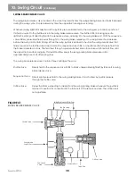
See Figure 38
The swing pump is an overcenter, variable displacement, axial pump. The pump housing is a cast case that
encases the rotary group and swashplate, stroking pistons and driveshaft. A port block bolts to the pump case
and contains pump ports, high pressure reliefs, charge pump assembly and reliefs, suction port for the charge
pump and a through drive for the auxiliary pumps. A separate torque control valve bolts to the pump case. A
hydraulic braking valve bolts to the torque control valve body.
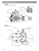
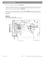
See figure 18
The charge pump and charge relief valve are required for swing circuit operation.
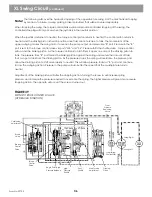
See Figure 17
The charge
pump relief valve is set at 400 PSI. It provides makeup hydraulic fluid for the loop and control fluid to the torque
control. During normal operation, some internal leakage exists in the pump and motor. Charge fluid is bled into
the low pressure side of the loop to replenish loop fluid that has been lost due to normal internal leakage. The
high pressure/anti cavitation reliefs in the port block will provide makeup fluid anytime loop pressure drops
below the charge relief setting. Charge circuit fluid is provided to the torque control valve to shift the pump.
Charge fluid going over relief is directed to the pump case to provide lubrication to the pump. The pump case is
always filled with fluid during operation (Case Fluid).
If the pump, motor, or loop are serviced or replaced the components and loop must be refilled with clean
hydraulic fluid before startup. If this is not done, bearing life and piston socket life can be seriously reduced.
Follow Start-up Procedure shown in
Section VII Main Hydraulic Pump.
These procedures must also be
adhered to if a vacuum has been applied to the hydraulic system.
At the opposite end of the loop from the swing motor is a bent axis fixed displacement motor. It consists of a
case, endcover, rotary group, port plate and driveshaft. It converts hydraulic energy into mechanical energy.
See Figure 31
The swing motor is attached to the swing parking broke and swing transmission. The parking brake is used to
hold the upperstructure stationary (when not swinging). It is strictly a static broke. It is not designed to stop the
upperstrudure swing.
XI. Swing Circuit
(continued)
31
Summary of Contents for XL4000
Page 2: ......
Page 73: ......
Page 76: ... 5MP ...
Page 145: ......
Page 146: ......
Page 160: ......
Page 161: ......
Page 162: ......
Page 175: ......
Page 176: ......
Page 177: ......
Page 178: ......
Page 192: ......
Page 193: ......
Page 194: ......
Page 207: ......
Page 208: ......
Page 210: ...500P ...
Page 229: ......
Page 230: ......
Page 245: ......
Page 246: ......
Page 247: ......
Page 248: ......
Page 265: ......
Page 266: ......
Page 267: ......
Page 268: ......
Page 280: ......
Page 281: ......
Page 282: ......
Page 297: ......
Page 298: ......
Page 299: ......
Page 300: ......
Page 301: ......
Page 302: ......
Page 303: ......
Page 304: ......

