VI. Filtration and Cooling Circuit
(continued)
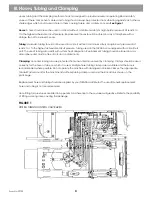
Backpressure Valve
Located in main control valve bank return line.
See Figure 11
Pressure setting relief 120 PSI
Prevents hydraulic fluid cavitation to control valves
FIGURE 12
HEAT EXCHANGER RADIATOR (OIL COOLER)
Heat Exchanger Radiator
(Oil Cooler)
Engine Radiator
l
l
l
Heat Exchanger Radiator (Oil Cooler)
Located in front of the engine radiator.
See Figure 12
Keep space between heat exchanger and engine clear of debris
Cools hydraulic fluid approximately 100° above ambient temperature
Receives fluid from Thermal Bypass Valve
Maximum flow through heat exchanger is 20.6 GPM
Directs fluid from the heat exchanger to the reservoir filter
Replace if system failure is caused by major contamination. It is very difficult to flush this and be certain it is
free of contaminants.
l
l
l
l
l
l
l
15
XL 4100/XL 5100 HYDRAULIC SYTEM OPERATIONS MANUAL
Form No. 29703
Summary of Contents for XL4000
Page 2: ......
Page 73: ......
Page 76: ... 5MP ...
Page 145: ......
Page 146: ......
Page 160: ......
Page 161: ......
Page 162: ......
Page 175: ......
Page 176: ......
Page 177: ......
Page 178: ......
Page 192: ......
Page 193: ......
Page 194: ......
Page 207: ......
Page 208: ......
Page 210: ...500P ...
Page 229: ......
Page 230: ......
Page 245: ......
Page 246: ......
Page 247: ......
Page 248: ......
Page 265: ......
Page 266: ......
Page 267: ......
Page 268: ......
Page 280: ......
Page 281: ......
Page 282: ......
Page 297: ......
Page 298: ......
Page 299: ......
Page 300: ......
Page 301: ......
Page 302: ......
Page 303: ......
Page 304: ......


