Form No. 29703
XL 4100/XL 5100 HYDRAULIC SYSTEM OPERATIONS MANUAL
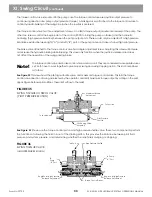
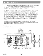
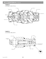
To simplify the swing control operation, right swing fluid path will be explained. Left swing will be similar in operation.
Note!
The right hand joystick controls the swing action on XL series machines. The joystick is connected directly to the torque
control valve.
See Figure 38
When swinging, pilot fluid enters the torque control valve at port Y1. A shuttle valve isolates the 2 Y ports, tells the
control valve that swing right has been selected. This directs pilot circuit fluid to the maximum torque relief valve.
Internal drillings route pilot fluid to the right hand end cap of the torque control piston, and to the left hand end cap
of the stroking control piston in the brake valve.
As pilot pressure rises in the torque control valve, it shifts the control piston against the spring in the left hand end
cap. While the control piston shifts, it meters fluid from the X3 port of the stroking piston to tank. The brake valve
control piston shifts to the right, and meters charge circuit fluid into the stroking piston via port X4 .
With the pressure rise on one side of the stroking piston, it shifts the swashplate to give pump output from port A to
the swing motor. As pressure rises at the A pan on the pump, a signal is sent to the torque control valve from the
MA port on the pump through port 15. This signal shifts a shuttle valve, and through internal drillings routes fluid
to the torque control piston and to the end of the braking piston.
At the braking piston, the high pressure fluid shifts it to the left, and closes off ports X3 from 14. High pressure
fluid at the torque control piston works with the spring in the left hand end cap to balance pilot pressure in the right
hand end cap (at a 14.5 to 1 ratio, 1450 PSI pump output pressure, will balance 100 PSI pilot pressure).
When balance is achieved between the high pressure and pilot pressure, the torque control piston shifts to the right
and blocks fluid from the stroking piston being vented to tank. At this point, pump output pressure (torque) is
balanced against pilot input pressure. The output pressure will remain constant until pilot pressure is altered.
When maximum pump output pressure setting is reached, the torque relief valve opens to limit pilot pressure. When
pilot pressure limit is reached, output pressure is limited to swing circuit pressure setting for your machine.
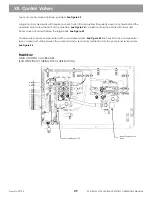
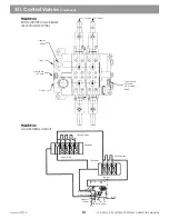
FIGURE 38
SWING TORQUE CONTROL VALVE
(HYDRAULIC FUNCTION)
XI. Swing Circuit
(continued)
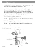
When in neutral, charge pressure is seen on both pump output ports and on both sides of
the stroking piston.
From
Pressure
Reducing
Valve
Cushioning
Adjustment
Brake Valve
Stroking
Control Piston
Swing Right
Swing Left
Right
Swing
From Swing
Suction Filter
Torque
Control
Piston
Begin Point/High
Pressure Balance
High
Pressure
SHuttle
Pilot
Shuttle
Max Torque
Adjustment
Stroking
Piston
35
Summary of Contents for XL4000
Page 2: ......
Page 73: ......
Page 76: ... 5MP ...
Page 145: ......
Page 146: ......
Page 160: ......
Page 161: ......
Page 162: ......
Page 175: ......
Page 176: ......
Page 177: ......
Page 178: ......
Page 192: ......
Page 193: ......
Page 194: ......
Page 207: ......
Page 208: ......
Page 210: ...500P ...
Page 229: ......
Page 230: ......
Page 245: ......
Page 246: ......
Page 247: ......
Page 248: ......
Page 265: ......
Page 266: ......
Page 267: ......
Page 268: ......
Page 280: ......
Page 281: ......
Page 282: ......
Page 297: ......
Page 298: ......
Page 299: ......
Page 300: ......
Page 301: ......
Page 302: ......
Page 303: ......
Page 304: ......


