XL 4000/XL 5000 SERIES
HYDRAULIC PRESSURE SETTING MANUAL
(Supplemental Pressures)
3
I. Pump Adjustment and Set-up
The main and swing pumps normally need no adjustment. If adjustment is required, precisely follow the
instructions given in this manual. Contact your Gradall Distributor or the Gradall factory before performing any
pump adjustment. This information is to be used for adjustment and set-up of the main and swing pumps. In most
situations, the pumps will not need to have the following settings checked or altered.
All other hydraulic circuit pressures must be tested and properly adjusted using the appropriate
Hydraulic Pressure
Setting Manual
for your machine before making any test on a pump. Procedures outlined in this
Supplemental
Pressures Manual
require the same tools as for the
Hydraulic Pressure Setting Manual
. Additional gauge
hosestwo P/N 7713-3259 hoses and one P/N 7713-4198 unionwill be required. These can be removed from
another gauge kit, or ordered separately.
If any pump adjustment screw is altered, a new seal cap must be installed. Two sizes of seal caps are used on
Gradall XL Series Excavators. Small blue caps are P/N 8093-4459; large blue caps are P/N 8093-4460.
II. Swing Pump Begin Point
The swing output pump begin point adjustment controls the point that the swing pump comes on stroke in relation to
joystick input pressure. This should only be adjusted if the machine exhibits problems with swing start, or pulsing
while swinging. This also should be adjusted if someone has tampered with the swing pump begin point screws.
Reseal swing pump begin point screws after adjustment.
Assemble one high pressure (10,000 PSI) and one low pressure (1000 PSI) test hose with gauge and connector.
Route both hoses across the machine so that they will be visible from the operators cab, i.e. the cradle stop at
the front of the frame on the left hand side of the cab.
Install the high pressure test hose to the outside test port of the swing pump.
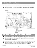
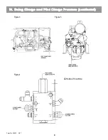
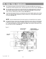
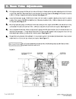
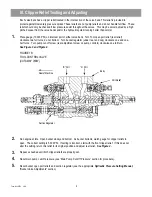
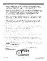
See Figure I & Figure 1A.
Remove the control pressure (low pressure) plug located between the high pressure test ports and install
adapter P/N 8656-1311 and test port P/N 7713-3089 in this port. Install the low pressure (1000 PSI) test hose in
this port.
See Figure 1 & Figure 1A.
Start the engine and run it at idle RPM. Remove the gauges from the test hoses and allow air to purge from
these hoses. Catch exhausting oil in an approved container. After air is purged from the hoses, reinstall
gauges to their proper hoses. Clean up any spilled oil.
Place bucket firmly on the ground, run engine at full RPM, then meter the swing right joystick.
Observe the pressure reading on both gauges. Whenever the low pressure gauge reads 90 PSI, swing
pressure on the high pressure gauge should rise to 500-550 PSI. This is the swing begin point. Adjust the
inside screw on the swing pump control to achieve proper right swing begin pressure.
See Figure 1 & Figure 1A.
NOTE!
This adjustment affects swing begin pressure. It does not affect the pilot signal to the pump.
1.
2.
3.
4.
5.
Form No. 29705 3/99
Summary of Contents for XL4000
Page 2: ......
Page 73: ......
Page 76: ... 5MP ...
Page 145: ......
Page 146: ......
Page 160: ......
Page 161: ......
Page 162: ......
Page 175: ......
Page 176: ......
Page 177: ......
Page 178: ......
Page 192: ......
Page 193: ......
Page 194: ......
Page 207: ......
Page 208: ......
Page 210: ...500P ...
Page 229: ......
Page 230: ......
Page 245: ......
Page 246: ......
Page 247: ......
Page 248: ......
Page 265: ......
Page 266: ......
Page 267: ......
Page 268: ......
Page 280: ......
Page 281: ......
Page 282: ......
Page 297: ......
Page 298: ......
Page 299: ......
Page 300: ......
Page 301: ......
Page 302: ......
Page 303: ......
Page 304: ......

