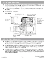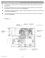
GRADALL XL 5200 machines use pressures that are appropriate for the application. Use this procedure to set
pressures on these machines. GRADALL Test Kit (P/N 7713-4197) contains all gauges, hoses and adapters required
to test machine functions. In addition to normal mechanic’s hand tools, metric wrenches (box, open end, and allen)
are required.
If any seal caps are removed while setting pressures, they must be replaced after the pressure is set. There are
two sizes of cap available. The small blue cap is available under P/N 8093-4459. The large blue cap is
available under P/N 8093-4460. The service technician should have a supply available before starting the
pressure setting procedure.
Hydraulic oil should be warmed to at least 120ø F before testing. Use the oil temperature display on the warning
monitor to check for proper temperature. Place cardboard cover over oil cooler at less than 30øF to help bring
temperature up. Traveling with the crawler will warm the oil quickly. Then cycle all functions to circulate warm oil
through the hydraulic system.
Engine RPM should be checked before testing any pressures. Use the RPM display on the warning monitor to
check RPM. High idle should be 2,400 RPM, low idle should be 800 RPM. Adjust as required before doing any
pressure testing.
NOTE! Cracking Pressure
Some functions require a special procedure for setting the port reliefs. These reliefs are set at “cracking”
pressure instead of full flow pressure. The following procedure will be used for the reliefs that are
affected. This procedure is used for bucket open and closed, hoist-up and boom-in port reliefs.
Rotate section regulator adjusting screw clockwise one and one-half turns, run engine at 1,000 RPM.
Slowly move joystick to meter in the function being checked. As circuit pressure rises, it will drop off
slightly as the load sense circuit begins to work, then rise to relief setting when the pump comes on
stroke. This is the “cracking’ pressure. At this point, you should also hear a hydraulic squeal.
When checking reliefs and section regulators on main valves, do not leave any function
bottomed longer than necessary to get reading. The reliefs and regulators will heat up very
rapidly and give inaccurate readings.
I. Testing and Adjusting
Form No. 29624 2/97
XL 5210 HYDRAULIC PRESSURE
SETTING MANUAL
1
Summary of Contents for XL4000
Page 2: ......
Page 73: ......
Page 76: ... 5MP ...
Page 145: ......
Page 146: ......
Page 160: ......
Page 161: ......
Page 162: ......
Page 175: ......
Page 176: ......
Page 177: ......
Page 178: ......
Page 192: ......
Page 193: ......
Page 194: ......
Page 207: ......
Page 208: ......
Page 210: ...500P ...
Page 229: ......
Page 230: ......
Page 245: ......
Page 246: ......
Page 247: ......
Page 248: ......
Page 265: ......
Page 266: ......
Page 267: ......
Page 268: ......
Page 280: ......
Page 281: ......
Page 282: ......
Page 297: ......
Page 298: ......
Page 299: ......
Page 300: ......
Page 301: ......
Page 302: ......
Page 303: ......
Page 304: ......

